


53
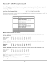
Serial Communication (RS232C)
The RS232C Interface signals for the Datamax-O’Neil printers are terminated on a 6 PIN RJ type data connector
located on the side of the printer. Six connections are provided from the Serial Interface to the host computer. A
minimum of two connections are required for operation, RXD – pin 3 and Common – pin 1.The proper baud rate and
protocol settings are required to communicate with the host device. The printer defaults to 115.2 K BAUD, 8 DATA
BITS, NO PARITY BIT, and two STOP BITs on initial power up. Two communication handshaking protocols are
supported by the Datamax-O’Neil printers, Serial Busy protocol and XON/XOFF protocols.
Serial Busy Protocol
For the serial busy handshaking mode, request to send printer input (RTS) and clear to send printer output (CTS) are
used to control data flow to and from the printer.
The RTS and CTS are considered to be valid or active when the signal level is positive (3 to 12VDC). A positive RTS
signal from the host device enables the printer. The RTS signal is monitored during data transmission from the printer to
the host device, the printer transmits data to the host device only if RTS input is high. The printer raises CTS output
when it is ready to accept data. The printer lowers CTS line when the print buffer has less than 256 unused locations.
XON/XOFF Protocol
For the XON/XOFF handshaking mode, the printer transmits XON (0x11) when it is ready to accept data, and XOFF
(0x13) when the print buffer has fewer than 256 unused locations. Under XON/XOFF protocol, the data flow from the
printer's serial port is halted on receipt of an XOFF from the Host device and resumed on receipt of a XON.
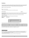
RS232C Connections
The RS232C Interface signals for the Datamax-O’Neil printers are terminated on a 6 PIN RJ25 type data connector
located at the back of the printer.
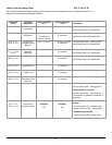
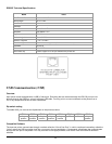
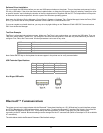
Six connections are provided from the Serial Interface to the host computer. The table below lists the Serial Interface
signals and pin-outs for the RJ25 connector while pin locations are shown in Figure below.
A minimum of two signal connections are required for operation, RXD - pin3 and Common - pin1.
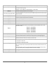
RJ25 Connector PIN # Functional Description Signal Name
3 RS232 from Host (INPUT) RXD
2 RS232 from Printer (OUTPUT) TXD
6 Request to send from Host (INPUT) RTS
4 Clear to send from Printer (OUTPUT) CTS
1, 5 Logic common COM