57
Wi-Fi Communication (Option)
The printer control card communicates with the Wi-Fi interface at 115.2 K Baud/sec for serial interface printers and 57.6 K for
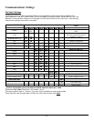
USB interface printers. To select the WiFi interface, Dip Switch # 1 or Dip Switch # 2 (See Dip Switch Settings table above) must
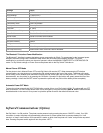
be ON and all other Dip Switches must be OFF. Below are the factory default settings of the Wi-Fi module. For more information
please refer to the 802.11g kit available on the Developer’s CD.
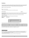
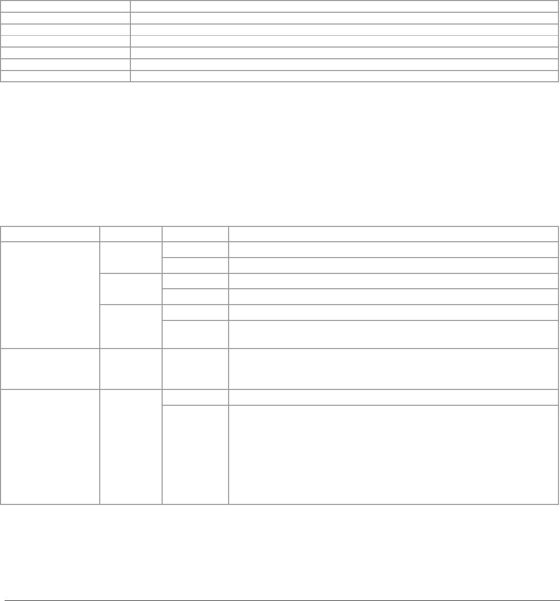
Settings Value
IP address 192.168.1.96
DHCP mode Disabled
Ad - Hoc mode Enabled
Infrastructure mode Disabled
SSID APEX# , where # matches the printer model
Tunnel port 23 (to send data to the 802.11g module use this port number)
Printer Status Indicator LED Panel
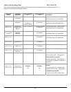
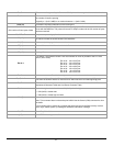
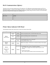
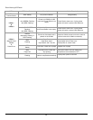
The table below describes the normal function of each of the Printer’s Status LEDs.
LED Status Condition Function
Flashing Power is ON and the printer is in RS232/USB or IRDA mode
GREEN
Steady Communicating with host
Flashing Power is ON and the printer is in Bluetooth mode
BLUE
Steady Transmitting/receiving
Flashing Power is ON and the printer is in 802.11b/g mode
LED # 1
Communication
Light Blue
Steady
Transmitting/Receiving in 802.11 mode OR
Printing Self test in 802.11 mode
LED # 2
Battery
AMBER
Steady
Battery being charged. The LED will turn off when the battery is fully charged
Steady Indicates that MCR or SCR is ready to accept data
LED # 3
Magnetic Card
Reader
&
Printer Error
GREEN
Flashing
Dip Switches 5 and 7 are ON – USB cable is plugged in.
Note: If USB is unplugged, LED will flash Amber until printer is reset
manually
Serial Firmware upload
Note: Firmware upload complete indicated by blue flashing LED #3


