


Replacing the Processor Module
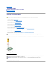
1. Align the pin-1 corner of the processor module with the pin-1 corner of the ZIF socket, then insert the processor module.
When the processor module is properly seated, all four corners are aligned at the same height. If one or more corners of the module are higher than the
others, the module is not seated properly.
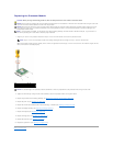
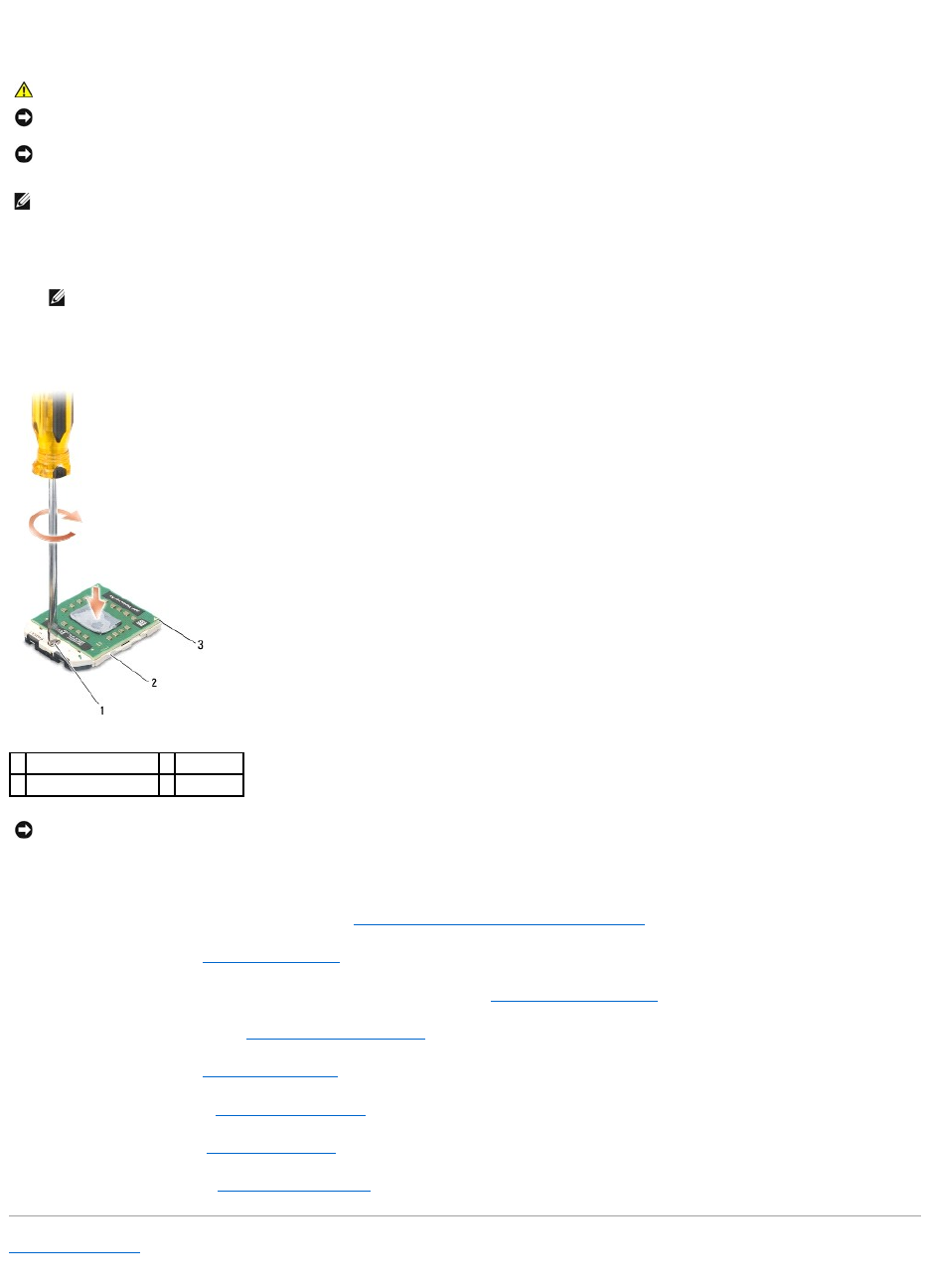
2. Tighten the ZIF socket by turning the cam screw clockwise to secure the processor module to the system board.
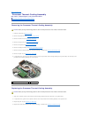
3. Replace the processor thermal-cooling assembly (see Replacing the Processor Thermal-Cooling Assembly).
4. Replace the palm rest (see Replacing the Palm Rest).
5. Replace the internal card with Bluetooth wireless technology, if installed (see Replacing the Bluetooth Card).
6. Replace the display assembly (see Replacing the Display Assembly).
7. Replace the keyboard (see Replacing the Keyboard).
8. Replace the hinge cover (see Replacing the Hinge Cover).
9. Replace the hard drive (see Replacing a Hard Drive).
10. Replace the optical drive (see Replacing the Optical Drive).
Back to Contents Page
CAUTION: Before you begin the following procedure, follow the safety instructions in the Product Information Guide.
NOTICE: Do not touch the processor die. Press and hold the processor down on the substrate on which the die is mounted while turning the cam screw
to prevent intermittent contact between the cam screw and processor.
NOTICE: Ensure that the cam lock is in the fully open position before seating the processor module. Seating the processor module properly in the ZIF
socket does not require force. A processor module that is not properly seated can result in an intermittent connection or permanent damage to the
microprocessor and ZIF socket.
NOTE: If a new processor is installed, you will receive a new thermal-cooling assembly, which will include an affixed thermal pad, or you will receive a
new thermal pad along with a tech sheet to illustrate proper installation.
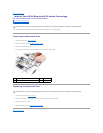
NOTE: The pin-1 corner of the processor module has a triangle that aligns with the triangle on the pin-1 corner of the ZIF socket.
1
ZIF-socket cam screw
2
ZIF socket
3
pin-1 corner
NOTICE: To avoid damage to the processor, hold the screwdriver so that it is perpendicular to the processor when turning the cam screw.