


58 Removing and Installing Parts
3
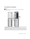
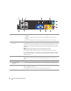
USB 2.0 connectors (2) Use the front USB connectors for devices that you connect occasionally, such as joysticks
or cameras (see "System Setup" on page 99 for more information on booting to a USB
device).
It is recommended that you use the back USB connectors for devices that typically
remain connected, such as printers and keyboards.
4 IEEE 1394 connector Attach high-speed serial multimedia devices, such as digital video cameras.
It is recommended that you use the back IEEE 1394 connector for devices that typically
remain connected, such as external hard drives and other storage devices.
5
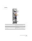
power button Press this button to turn on the computer.
NOTICE: To avoid losing data, do not use the power button to turn off the computer.
Instead, perform an operating system shutdown.
6
power light The power light illuminates and blinks or remains solid to indicate different states:
• No light — The computer is turned off.
• Steady green — The computer is in a normal operating state.
• Blinking green — The computer is in a power-saving state.
• Blinking or solid amber — See "Power Problems" on page 38.
7
front-panel door release
button
Press this button to access the front-panel connectors.
8
microphone connector
Use the pink microphone connector to attach a personal computer microphone for
voice or musical input into a sound or telephony program.
On computers with a sound card, the microphone connector is on the card.
9
headphone connector
Use the green headphone connector to attach headphones and most kinds of speakers.
10
hard-drive activity light
The hard drive activity light is on when the computer reads data from or writes data to
the hard drive. The light might also be on when a device such as a CD player is
operating.
11
diagnostic lights
For more information on what each diagnostic light means, see "Diagnostic Lights" on
page 45.
12
front-panel door
This panel covers the CD/DVD drive, the Media Card Reader, and the optional floppy
drive.