


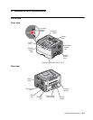


Locations and connections 5-3
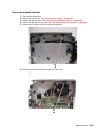
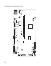
Note: See the wiring diagram at back of book.
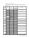
These values were measured with all connections made (plugged) or with only one connector at a time
unplugged to expose the pins. Always disconnect and connect with the printer power off. Otherwise, the values
below may not match.
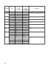
Connector Pin # Value
cable plugged
Value
cable unplugged
(if different)
Comments
J4 1 Ground Cartridge
(The front access door must be closed.)
21.7 Vdc
3, 4 3.3 V dc
J5 1, 3, 5, 6 3.3 V dc Operator panel
25.0 Vdc
4, 7 Ground
J100 1 > 0 V dc 5 V dc Printhead
2, 3 5 V dc
4, 5, 6, 7 Ground
J7 1 5 V dc (door closed) Open door sensor
0 V dc (door open)
25 Vdc
3Ground
J8 1, 10 5 V dc LSU
92.9 Vdc
J9 1 24 V dc 0 V dc Cooling fan
2 24 V dc
J10 1 24 V dc 24 V dc Duplex solenoid
2 24 V dc 0 V dc
J11 1 5 V dc Narrow media sensor
25 Vdc 5 Vdc
3Ground
J12 1 5 V dc Thermistor
2Ground
J13 1 0.6 V dc Toner level sensor
2Ground
30 Vdc
J14 1 > 0 V dc 5 V dc Fuser exit sensor
25 Vdc
3Ground
J17 1, 4 0.1 V dc 5 V dc Main gear drive motor
2, 3, 6 5 V dc
5Ground
7, 8, 9 24 V dc
J19 USB port