


28 Cabling Your Cluster Hardware
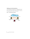
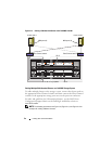
Cabling a SAN-Attached Cluster to a Dell/EMC Storage System
The cluster nodes attach to the storage system using a redundant switch
fabric and Fibre optic cables with duplex LC multimode connectors.
The switches, the HBA ports in the cluster nodes, and the SP ports in the
storage system use duplex LC multimode connectors. The connectors consist
of two individual fibre optic connectors with indexed tabs that must be
inserted and aligned properly in the small form-factor pluggable (SFP)
module connectors on the Fibre Channel switches and the connectors on the
cluster nodes and storage systems.
Each HBA port is cabled to a port on a Fibre Channel switch. One or more
cables connect from the outgoing ports on a switch to a storage processor on a
Dell/EMC storage system.
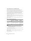
Table 2-3 provides information for cabling your storage system to the Fibre
Channel switches.
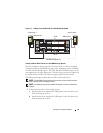
NOTE: Adding more cables from the storage system to the switches can increase
the I/O bandwidth and high availability of data. Although the CX4-960 has a
maximum of 12 front-end fibre channel ports per SP, only 8 of them can be
connected to fibre channel switches.
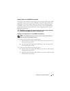
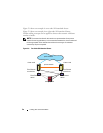
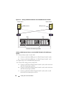
Figure 2-10 illustrates the method for cabling a SAN-attached cluster to the
CX4-120 and CX4-240 storage systems.
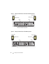
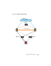
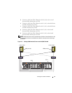
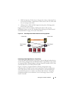
Figure 2-11 illustrates a method for cabling a SAN-attached cluster to a CX4-
480 storage system.
Figure 2-12 illustrates a method for cabling a SAN-attached cluster to a
CX4-960 storage system.
Table 2-3. Storage System Cabling Description
Storage System Front-end Fibre
Channel ports per
SP
Fibre Optic
Cables Required
Cabling
Description
CX4-120, CX4-240 Two to six ports Four to twelve Attach one cable
from each storage
processor port to
the Fibre Channel
switch.
CX4-480 Four to eight ports Eight to sixteen
CX4-960 Four to twelve
ports
Eight to sixteen