


132 Installing System Components
10
Enter the correct time and date in the System Setup program's
Time
and
Date
fields.
11
Exit the System Setup program.
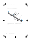
Control Panel Assembly
NOTE: The LCD control panel assembly consists of two separate modules—the
display module and the control panel circuit board. Use the following instructions to
remove and install either module.
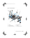
Removing the Control Panel Board Assembly and the Control Panel
Display Module
CAUTION: Many repairs may only be done by a certified service technician. You
should only perform troubleshooting and simple repairs as authorized in your
product documentation, or as directed by the online or telephone service and
support team. Damage due to servicing that is not authorized by Dell is not covered
by your warranty. Read and follow the safety instructions that came with the
product.
1
If installed, remove the optional front bezel. See "Front Bezel (Optional)"
on page 77.
2
Turn off the system and attached peripherals, and disconnect the system
from the electrical outlet and peripherals.
3
Open the system. See "Opening the System" on page 78.
4
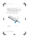
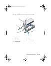
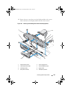
Disconnect the control panel cable at the back of the control panel board.
See Figure 3-24.
CAUTION: Do not pull on the cable to unseat the connector. Doing so can damage
the cable.
a
Press the metal tabs on the ends of the cable connector.
b
Gently work the connector out of the socket.
c
Remove the USB connector cable, the display module cable and the
power cable.
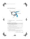
5
Remove the two screws that secure the control panel board to the system
chassis and remove the board.
This completes the removal procedure for the LED control panel.
R310HOM.book Page 132 Thursday, March 4, 2010 1:03 AM