


About Your System 19
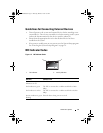
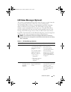
Back-Panel Features and Indicators
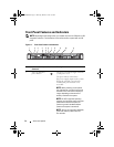
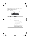
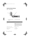
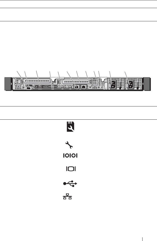
Figure 1-4 shows the controls, indicators, and connectors located on the
system's back panel.
Figure 1-4. Back-Panel Features and Indicators
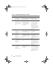
Blinks green three seconds, amber three
seconds, and off six seconds.
Rebuild aborted
Item Indicator, Button, or
Connector
Icon Description
1 VFlash media slot
(optional)
Connects an external SD memory card
for the optional iDRAC6 Enterprise
card.
2 iDRAC6 Enterprise
port (optional)
Dedicated management port for the
optional iDRAC6 Enterprise card.
3 Serial connector Connects a serial device to the system.
4 Video connector Connects a VGA display to the system.
5 USB connectors (2) Connect USB devices to the system.
The ports are USB 2.0-compliant.
6 Ethernet connectors
(2)
Embedded 10/100/1000 NIC
connectors.
7 PCIe slots (2) PCI Express (generation 2) expansion
slot (full-height, half-length).
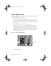
Drive-Status Indicator Pattern (RAID Only) Condition
Gb1
Gb2
2
1
1
2
3
4
7
8
9
10
11
12
5 6
R310HOM.book Page 19 Thursday, March 4, 2010 1:03 AM