


Installing System Components 133
6
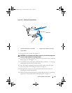
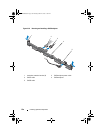
Remove the two screws that secure the display module to the system
chassis and remove the display module from the chassis cutout.
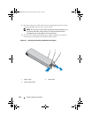
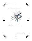
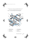
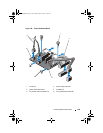
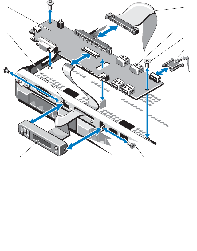
Figure 3-24. Removing and Installing Control Panel Assembly (Optional)
1 display module cable 2 control panel board
3 control panel data cable 4 internal USB Connector
5 mounting screws 6 power cable
7 front panel screw (2) 8 LCD display module
1
3
5
2
6
7
8
4
R310HOM.book Page 133 Thursday, March 4, 2010 1:03 AM