


84 Removing and Installing Parts
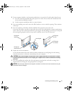
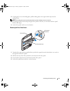
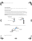
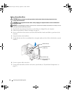
Connecting Drive Cables
When you install a drive, you connect two cables—a DC power cable and a data cable—to the back of
the drive and to the system board.
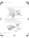
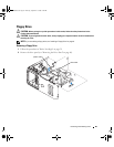
Drive Interface Connectors
Most interface connectors are keyed for correct insertion; that is, a notch or a missing pin on one
connector matches a tab or a filled-in hole on the other connector. Keyed connectors ensure that the pin-1
wire in the cable (indicated by the colored stripe along one edge of the IDE cable—serial ATA cables do
not use a colored stripe) goes to the pin-1 end of the connector. The pin-1 end of a connector on a board
or a card is usually indicated by a silk-screened “1” printed directly on the board or card.
NOTICE: When you connect an IDE interface cable, do not place the colored stripe away from pin 1 of the
connector. Reversing the cable prevents the drive from operating and could damage the controller, the drive, or both.
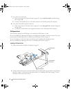
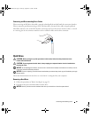
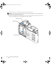
Power Cable Connector
To connect a drive using the power cable, locate the power input connector on the system board.
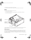
Serial ATA Connector
interface cable
interface connector
power cable
power input
connector
WD846bk2.book Page 84 Thursday, September 14, 2006 2:40 PM