642 Configuring Access Control Lists
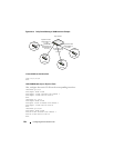
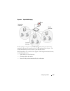
Figure 20-14. Policy Based Routing on VLAN Interfaces Example
Create VLANs 10, 20, 30 and 40
vlan 10,20,30,40
exit
Add VLAN Membership to Physical Ports
Also, configure the native VLAN on the corresponding interfaces:
interface gi1/0/2
switchport mode trunk
switchport trunk allowed vlan remove 1
switchport trunk native vlan 10
exit
interface gi 1/0/4
switchport mode trunk
swithport trunk allowed vlan remove 1
switchport trunk native vlan 20
exit
interface gi1/0/22
switchport mode trunk
switch trunk allowed vlan remove 1
switch trunk native vlan 30
exit
Layer 3 Switch
L2 Switch
L2 Switch
VLAN 10
VLAN 20
L2 Switch
VLAN 30
L2 Switch
VLAN 40
Physical Port 1/0/2
VLAN Interface 10
1.1.1.1/24
Physical Port 1/0/4
VLAN Interface 20
2.2.2.1/24
Physical Port 1/0/22
VLAN Interface 30
3.3.3.1/24
Physical Port 1/0/24
VLAN Interface 40
4.4.4.3/24


