


DGS-3024 Gigabit Ethernet Switch Manual
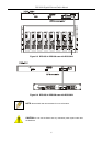
Figure 3-3. Side panel views of the Switch
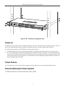
• The system fans are used to dissipate heat. The sides of the system also provide heat vents to serve the same purpose.
Do not block these openings, and leave at least 6 inches of space at the rear and sides of the Switch for proper
ventilation. Be reminded that without proper heat dissipation and air circulation, system components might overheat,
which could lead to system failure.
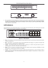
LED Indicators
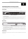
The LED indicators of the Switch include Power, Console, RPS, Speed, and Link/Activity. The following shows the LED
indicators for the Switch along with an explanation of each indicator.
Figure 3-4. LED indicators
• Power – This indicator on the front panel lights solid green when the system is powered up and remains dark when the
system is not powered on.
• RPS – This indicator is lit solid amber when the external Redundant Power Supply is in operation and remains dark
when it is not in use or the main power is working normally.
• Console – This indicator blinks green when the system is booting up. It remains solid green when the system is
operating properly. The LED is solid amber when the POST fails.
• Speed – This row of indicators will light solid green when the connection speed is operating at 1000 Mbps. An unlit
LED indicates a connection speed of either 10 or 100 Mbps.
• Link/Act – This row of indicators for the 24 copper ports light solid green when there is a secure connection (or link) to
a device on any of the ports. The LEDs blink green whenever there is reception or transmission (i.e. Activity--Act) of
data occurring on a port.
8