


1 Product Introduction D-Link Web Smart Switch User Manual
Po
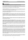
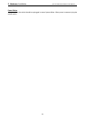
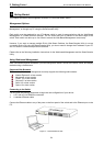
wer: The power port is where to connect the AC power cord.
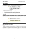
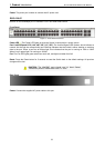
DGS-1210-52
48-Port 10/100/1000Mbps plus 4 1000Base-T/SFP Slot Web Smart Switch.
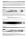
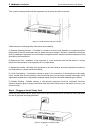
Front Panel
Figure 1.2 – DGS-1210-52 Front Panel
Power LED
: The Power LED lights up when the Switch is connected to a power source.
Port Link/Act/Speed LED (1-48, 49F, 50F, 51F, 52F): The Link/Act/Speed LED flashes, which indicates a
network link through the corresponding port. Blinking indicates that the Switch is either sending or receiving
data to the port. When a port has an amber light, this indicates that the port is running on 10M or 100M.
When it has a green light it is running on 1000M.
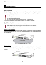
Fan: The Fan LED lights green when fans work well, and lights red when fans fail.
Reset: Press the Reset button for 5 seconds to reset the Switch back to the default settings. All previous
changes will be lost.
CAUTION: The MiniGBIC ports should use UL listed Optical
Transceiver product, Rated Laser Class I. 3.3Vdc.
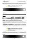
Rear Panel
Figure 1.3 – DGS-1210-52 Rear Panel
Power: Connect the supplied AC power cable to this port.
5
5