


5 Configuration D-Link Web Smart Switch User Manual
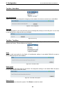
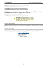
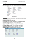
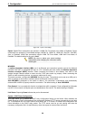
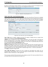
Figure 5.21 – System > Port Settings
Speed: Gigabit Fiber connections can operate in 1000M Full Force Mode, Auto Mode or Disabled. Copper
connections can operate in Forced Mode settings (1000M Full, 100M Full, 100M Half, 10M Full, 10M Half),
Auto, or Disabled. 100M Fiber connections support 100M Full Force Mode, 100M Half Force Mode, or
Disabled. The default setting for all ports is Auto.
NOTE: Be sure to adjust port speed settings
appropriately after changing the connected cable
media types.
MDI/MDIX:
A medium dependent interface (MDI) port is an Ethernet port connection typically used on the Network
Interface Ca
rd (NIC) or Integrated NIC port on a PC. Switches and hubs usually use Medium dependent
interface crossover (MDIX) interface. When connecting the Switch to end stations, user have to use
straight through Ethernet cables to make sure the Tx/Rx pairs match up properly. When connecting the
Switch to other networking devices, a crossover cable must be used.
This switch provides a configurable MDI/MDIX function for users. The switches can be set as an MDI port in
orde
r to connect to other hubs or switches without an Ethernet crossover cable.
Auto MDI/MDIX is designed on the switch to detect if the
connection is backwards, and automatically
chooses MDI or MDIX to properly match the connection. The default setting is “Auto” MDI/MDIX.
Flow Control: You can enable this function to mitigate the traffic congestion. Ports configured for full-duplex
use 802.3x flow control, half-duplex ports use backpressure flow control. The default setting is Disabled.
Link Status: Reporting Down indicates the port is disconnected.
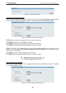
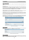
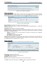
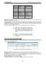
System > DHCP Auto Configuration
This page allows you to enable the DHCP Auto Configuration feature on the Switch. When enabled, the
Switch becomes a DHCP client and gets the configuration file from a TFTP server automatically on next boot
up. To accomplish this, the DHCP server must deliver the TFTP server IP address and configuration file
name information in the DHCP reply packet. The TFTP server must be up and running and store the
necessary configuration file in its base directory when the request is received from the Switch.
28