


EM78P458/459
OTP ROM
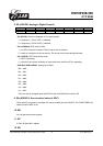
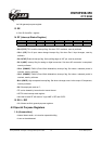
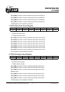
8. R9 (ADCON: Analog to Digital Control)
7 6 5 4 3 2 1 0
- - IOCS ADRUN ADPD ADIS2 ADIS1 ADIS0
• Bit 7:Bit 6 Unemployed, read as ‘0’;
• Bit 5(IOCS): Select the Segment of IO control register.
1 = Segment 1 ( IOC51~IOCF1 ) selected;
0 = Segment 0 ( IOC50~IOCF0 ) selected;
• Bit 4 (ADRUN): ADC starts to RUN.
1 = an A/D conversion is started. This bit can be set by software;
0 = reset on completion of the conversion. This bit can not be reset though software;
• Bit 3 (ADPD): ADC Power-down mode.
1 = ADC is operating;
0 = switch off the resistor reference to save power even while the CPU is operating.
• Bit2:Bit0 (ADIS2:ADIS0): Analog Input Select.
000 = AN0;
001 = AN1;
010 = AN2;
011 = AN3;
100 = AN4;
101 = AN5;
110 = AN6;
111 = AN7;
They can only be changed when the ADIF bit and the ADRUN bit are both LOW.
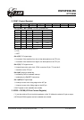
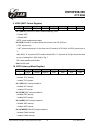
9. RA (ADDATA: the converted value of ADC)
When the A/D conversion is complete, the result is loaded into the ADDATA. The START//END bit is
cleared, and the ADIF is set.
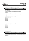
10. RB
An 8-bit general-purpose register.
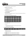
11. RC
A 2-bit, Bit 0and Bit 1 register.
12. RD
This specification is subject to change without prior notice. 07.01.2003 (V1.3)
12