


EM78P458/459
OTP ROM
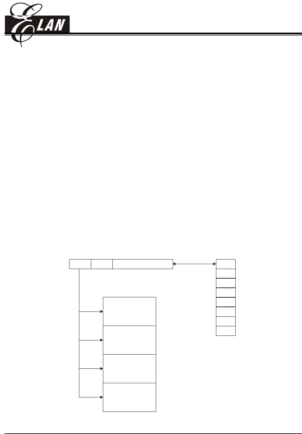
• The contents of R2 are set to all "0"s upon a RESET condition.
• "JMP" instruction allows the direct loading of the lower 10 program counter bits. Thus, "JMP" allows
PC to jump to any location within a page.
• "CALL" instruction loads the lower 10 bits of the PC, and then PC+1 is pushed into the stack. Thus,
the subroutine entry address can be located anywhere within a page.
• "RET" ("RETL k", "RETI") instruction loads the program counter with the contents of the top of stack.
• "ADD R2, A" allows a relative address to be added to the current PC, and the ninth and tenth bits of
the PC are cleared.
• "MOV R2, A" allows to load an address from the "A" register to the lower 8 bits of the PC, and the
ninth and tenth bits of the PC are cleared.
• Any instruction that is written to R2 (e.g. "ADD R2, A", "MOV R2, A", "BC R2, 6",⋅⋅⋅⋅⋅) will cause the
ninth bit and the tenth bit (A8~A9) of the PC to be cleared. Thus, the computed jump is limited to the
first 256 locations of a page.
• In the case of EM78P458/459, the most two significant bits (A11 and A10) will be loaded with the
content of PS1 and PS0 in the status register (R3) upon the execution of a "JMP", "CALL", or any
other instructions set which write to R2.
• All instructions are single instruction cycle (fclk/2 or fclk/4) except for the instructions which write to
R2, need one more instruction cycle.
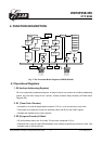
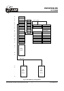
A9 ~ A8A11~A10 A7 ~ A0
Page 0
Page 1
Page 2
Page 3
000
3FF
400
7FF
BFF
FFF
C00
800
00
01
10
11
CALL K
RET
RETI
RETL K
Stack 0
Stack 1
Stack 2
Stack 3
Stack 4
Stack 5
Stack 6
Stack 7
Fig. 3 Program Counter Organization
This specification is subject to change without prior notice. 07.01.2003 (V1.3)
9