


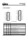

EM78P458/459
OTP ROM
An 8-bit general-purpose register.
13. RE
A 2-bit, Bit 0 and Bit 1 register.
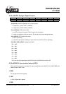
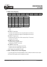
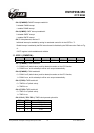
14. RF (Interrupt Status Register)
7 6 5 4 3 2 1 0
- CMPIF PWM2IF PWM1IF ADIF EXIF ICIF TCIF
“1” means interrupt request, and “0” means no interrupt occurs.
• Bit 0 (TCIF) TCC overflow interrupt flag. Set when TCC overflows, reset by software.
• Bit 1 (ICIF) Port 6 input status change interrupt flag. Set when Port 6 input changes, reset by
software.
• Bit 2 (EXIF) External interrupt flag. Set by falling edge on /INT pin, reset by software.
• Bit 3 (ADIF) Interrupt flag for analog to digital conversion. Set when AD conversion is completed,
reset by software.
• Bit 4 (PWM1IF) PWM1 (Pulse Width Modulation) interrupt flag. Set when a selected period is
reached, reset by software.
• Bit 5 (PWM2IF) PWM2 (Pulse Width Modulation) interrupt flag. Set when a selected period is
reached, reset by software.
• Bit 6 (CMPIF) High-compared interrupt flag. Set when a change occurs in the output of Comparator,
reset by software.
• Bit 7 Unemployed, read as ‘0’;
• RF can be cleared by instruction but cannot be set.
• IOCF0 is the interrupt mask register.
• Note that to read RF will result to "logic AND" of RF and IOCF0.
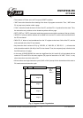
15. R10 ~ R3F
• All of these are 8-bit general-purpose registers.
4.2 Special Purpose Registers
1. A (Accumulator)
• Internal data transfer, or instruction operand holding
• It can not be addressed.
This specification is subject to change without prior notice. 07.01.2003 (V1.3)
13