


EM78P458/459
OTP ROM
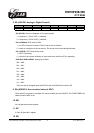
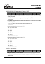
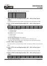
4. IOC90 (GCON: I/O Configuration & Control of ADC )
7 6 5 4 3 2 1 0
OP2E OP1E G22 G21 G20 G12 G11 G10
• Bit 7 ( OP2E ) Enable the gain amplifier which input is connected to P64 and output is connected to
the 8-1 analog switch.
0 = OP2 is off ( default value ), and bypasses the input signal to the ADC;
1 = OP2 is on.
• Bit 6 ( OP1E ) Enable the gain amplifier whose input is connected to P60 and output is connected to
the 8-1 analog switch.
0 = OP1 is off (default value), and bypasses the input signal to the ADC;
1 = OP1 is on.
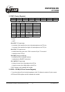
• Bit 5:Bit 3 (G22 and G20): Select the gain of OP2.
000 = IS x 1 (default value);
001 = IS x 2;
010 = IS x 4;
011 = IS x 8;
100 = IS x 16;
101 = IS x 32;
Legend: IS = the input signal
• Bit 2:Bit 0 (G12 and G10 ): Select the gain of OP1.
000 = IS x 1 (default value);
001 = IS x 2;
010 = IS x 4;
011 = IS x 8;
100 = IS x 16;
101 = IS x 32;
Legend: S = the input signal
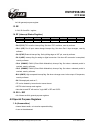
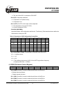
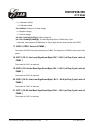
5. IOCA0 ( AD-CMPCON ):
7 6 5 4 3 2 1 0
VREFS CE COE IMS2 IMS1 IMS0 CKR1 CKR0
• Bit 7: The input source of the Vref of the ADC.
0 = The Vref of the ADC is connected to Vdd (default value), and the P53/VREF pin carries out the
function of P53;
This specification is subject to change without prior notice. 07.01.2003 (V1.3)
15