


TESTING & SERVICE
(continued)
3-- 2
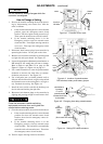
MANUAL LOAD TRANSFER
This procedure will manually transfer the load if the
controller is disconnected.
Do not manually operate the transfer switching
device until both power sources are
disconnected: open b oth circuit breakers.
1. Open normal and emergency source circuit
breakers.
2. Use the maintenance handle to manually operate
transfer switching device to the opposite source.
See page 1–4, Manual Operation Test.
3. If the transfer switching device is in the
Emergency posit ion manually start the engine
generator and t h en close the e mergency source
circuit breaker.
TROUBLE- SHOOTING
Note the control features that are activated or
furnished on the switch and review their operation.
Refer to Section 5, Control Features.
Proceed with care! The automatic transfer
switching equipment is energized.
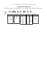
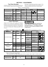
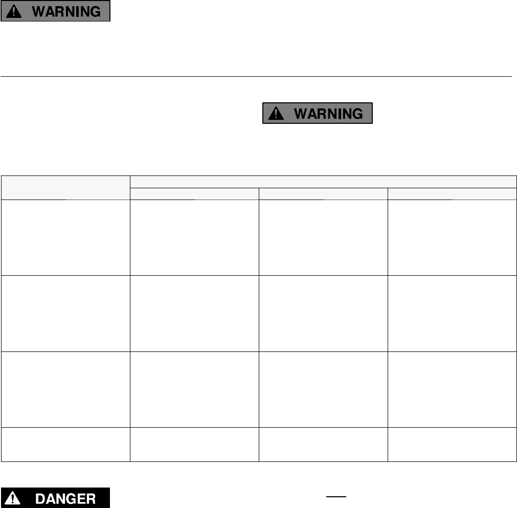
Table 3-1. Trouble-Shooting Checks.
P
R
O
B
L
E
M
CHECK IN NUMERICAL SEQUENCE
P
R
O
B
L
E
M
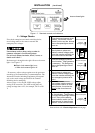
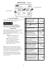
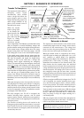
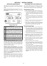
1OPERATION 2 GEN-SET 3VOLTAGE
Gen-Set does not start when
the TRANSFER SWITCH TEST
butto n is pressed and held for
15 seconds or when the
normal so urce fails.
Hold the TRANSFER SWITCH
TEST button 15 sec. or the
outage must be long enough
to allow for the 1 or 3 sec.
Momentary Normal Source
Outage Delay plus engine
cranking and start ing time.
Starting control must be in
automatic position. Batteries
must be charged and
connec ted. Chec k wiring to
engine starting cont acts.
—
Transfer switching device
does not transfer the load to
emergency source after the
gen-set starts.
Wait for T ransfer to Emergen-
cy Delay (0 to 5 min.) to time
out. For immediate transfer,
press the BYPASS TIME
DELAY button. If Motor Load
Transfer is active, wait for in-
phase condition (see below).
Generator output circuit
breaker must be closed.
Generator frequency must be
at least 95% of nominal
(48Hzfora50Hzsystem).
Voltmeter should read at leas t
90% of nominal phase to
phase voltage between
transfer switch terminals U2
and W2 (or L1 and L5 for 2
pole switches). *
* These are factory settings.
Transfer switching device
does not transfer the load to
normal source when no rmal
returns or when TRANSFER
SWITCH TEST button is
released.
Wait for Retransfer to Normal
Delay (1 sec. to 30 min.) to
time out. For immediate re–
transfer, press BYPASS TIME
DELAY button. If Motor Load
Transfer is active, wait for in-
phase condition (see below).
—
Voltmeter should read at least
90% of nominal phase to
phase voltage between
transfer switching device
terminalsV1andW1,W1and
U1, and U1 and V1 (or L2 and
L6 for 2 pole switches).
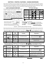
Gen-Set does not stop after
load retransfer to the normal
source.
Wait for the 5 minute
Unloaded Running Delay to
time out.
Starting control must be in
automatic position.
—
Trouble-Shooting the Motor Load Transfer Feature (refer to page 5–3)
Use extreme caution when using a m eter to
measure voltages in the following steps. Do not
touch power termi nal s; sh ock, b ur ns, or death
could result !
1. Connect a voltmeter (set for twice system
phase–to–phase voltage) between transfer
switching device terminals U1 and U2 (for 3 pole)
or L1 and L2 (for 2 pole).
2. Manually start generator. Voltmeter needle should
sweep back and forth at a regular rate between 0
and about twice system voltage.
3. Press and hold
the Transfer Test button. The load
should transfer to emergency source when meter
needle is near 0 volts. If transfer does not occur,
Motor Load Transfer feature is not operating.
4. Release the Transfer Test button. The load should
retransfer back to the normal source after the
Retransfer to Normal Delay,ifused. Theretransfer
should occur when the needle is near 0 volts. If
retransfer does not occur after the time delay, the
Motor Load Transfer feature is not operating.
5. For immediate retransfer, press the Bypass Time
Delay button. Then disconnect the voltmeter.
If the problem is isolated to circuits on the controller or the transfer switching device, call your local ASCO
Power Technolo gi e s sa le s o f f i ce . Furni sh Se ria l No., B i ll o f M a te ria l (B O M ) No ., & Ca t a lo g No . fr o m th e
transfer switching device nameplate.