


INSTALLATION (continued)
1-- 2
De–energize the conductors before making
any line or auxiliary circuitry connections.
Be sure that Normal and Emergency line
connections are in proper phase rotation.
Place engine g enerator starting control in the
OFF position. Make sure engine generator is not
in operation.
Power connections
A Wiring Diagram is furnished with the Series 200
ATSE. All wiring must be made in accordance with the
local codes.
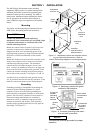
Do not run cables in front of the transfer switching
device. Conductors can be bundled on the right side of
the transfer switching device. Maintain proper electrical
clearance between the live metal parts and grounded
metal: 13 mm minimum.
It is not necessary to remove the barriers from the
transfer switching device to install the conductors. If
you do remove them, however, be sure to reinstall the
barriers carefully.
Connect main source and load conductors to clearly
marked power terminals on the transfer switching
device. Be careful when stripping insulation from the
conductors; avoid nicking or ringing the conductor.
Remove surface oxides from conductors by cleaning
with a wire brush. Follow conductor manufacturer’s
instructions when aluminum conductor is used. Apply
joint compound to conductor, then carefully wipe away
excess compound. Tighten the terminals to the torque
specified on the label on the transfer switching device.
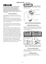
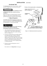
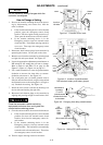
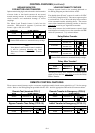
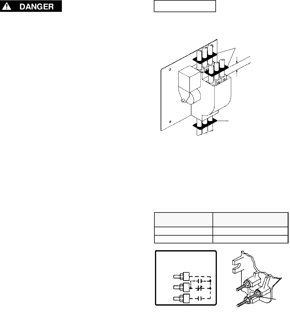
Three conductor spacers are included wi th 150, 200,
and 230 ampere transfer switching devices. When
installing power conductors, run the m through the
conductor spacers as shown in Figure 1–4. Position the
spacers wi thin 38 mm of the power termina ls.
NOTICE
Three conductor spacers must be located as
shown for 150, 200, and 230 ampere transfer
switching devices.
conductor spacer
conductor spacers
38 mm approximate
Figure 1-4. Required conductor spacers for
150, 200, & 230 amp transfer switching devices.
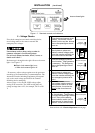
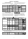
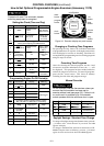
Engine Starting Contacts
The engine control contact connecti ons (if used) are
located on the transfer switching device. Connect signal
wires to appropriate terminals as specified i n Table A
and shown in Figure 1–5.
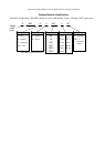
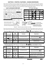
Table A. Engine start connections
When normal
source fails
Termin als on
transfer switching device
contact closes TB1 and TB2
contact opens TB1 and TB3
TB 1
TB 2
TB 3
ENGINE STARTING CONTACTS
( SHOWN DE–ENERGIZED )
TOP
STUD
MIDDLE
STUD
BOTTOM
STUD
1
2
3
TS
NR
NR
Figure 1-5. Engine starting contact label and
location on left side of transfer switching device.
Interconnecting harness
Connect the plug–in harness (two plugs) from the
transfer switching device to left side of the controller, if
not already connected.
Auxiliary Circuits
Connect auxiliary circuit wires (if necessary) to
appropriate terminals by referring to the Wiring
Diagram.