


INSTALLATION (continued)
1-- 3
Functional Test
The Functional Test consists of three checks: manual
operation, voltage checks, and electrical operation.
NOTICE
Do these checks in the order presented to avoid
damaging the automatic transfer switching
equipment.
Read all instructions on the Wiring Diagrams and lab el s
affixed to the ATS . Note the control features that are
pro v id ed and rev iew th eir op er atio n bef or e pro ceed in g .
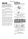
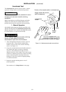
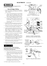
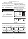
1 – Manual Operation
A detachab l e manual oper ator handl e is prov ided on the
Tran s fe r Sw itc h in g de v ic e fo r mai n tenan ce pu r pos e s on ly.
Manual operation of the transfer switching device must
be checked before it is operated electrically.
Do not manually operate the transfer switching
device until both power sources are
disconnected: open both circuit breakers.
1. After deenergizing both power sources, open the
enclosure door. Locateandthemaintenance
handle on the left side of the transfe r switching
device. See Figure 1–6.
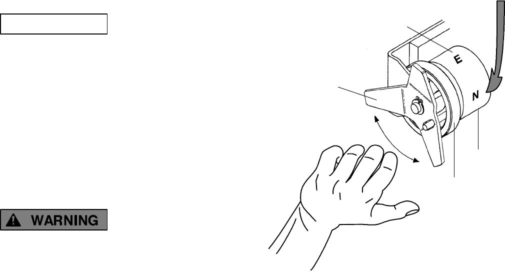
2. Grasp the attached maintenance handle and turn it
with thumb and fingers as shown to manually
operate it. T he maintenance handle turns the
opposite direction of t he weight. Turn it up or down
as shown to manually operate t he transfer switching
device. It should operate smoothly without any
binding. If it does not, check for shi pping damage
or construction debris.
3. Return the transfer switc h ing devic e to the N
(normal) position.
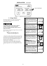
Now continue to 2–VoltageCheckson next page.
maintenance
handle
With ALL POWER OFF grasp
maintenance handle and turn it
quickly with your thumb and fingers.
weight marked N (normal)
and E (emergency)
floating
weight
weight
P osition of the tr ansf er switch i s in di cated here
Figure 1-6. Maintenance handle and positions.