


SECTION 1 INSTALLATION
1-- 1
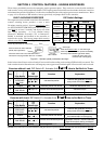
The A SCO Series 200 automatic transfer switch ing
equipmen t ( ATSE ) c onsists of a tran sfer switching device,
monitoring and transfer control device (controller), and
membrane controls (for door mounting). The ATSE is
factor y tes ted. I nstall ation requires mounting the devices
into an appropriate size enclo sure and conn ection of
pow er conduc tors, engine start signal wires, and auxiliary
circuits.
Mounting
The Outline and Mounting Diagram furn is h ed with the
AT S E show s all moun tin g detail s and instru ction s .
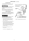
NOTICE
Protect the automatic transfer switching
equipment from construction grit and metal chips
to prevent malfunction or shortened life of the
transfer switching device.
Mount the transfer switch vertically in the back of the
enclosure as shown on the Outline and Mounting
Diagram provided. Level all mounting points of the
rigid supporting structure by using flat washers behind
the holes to avoid forced distortion of t he transfer
switch.
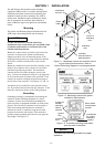
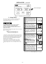
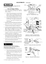
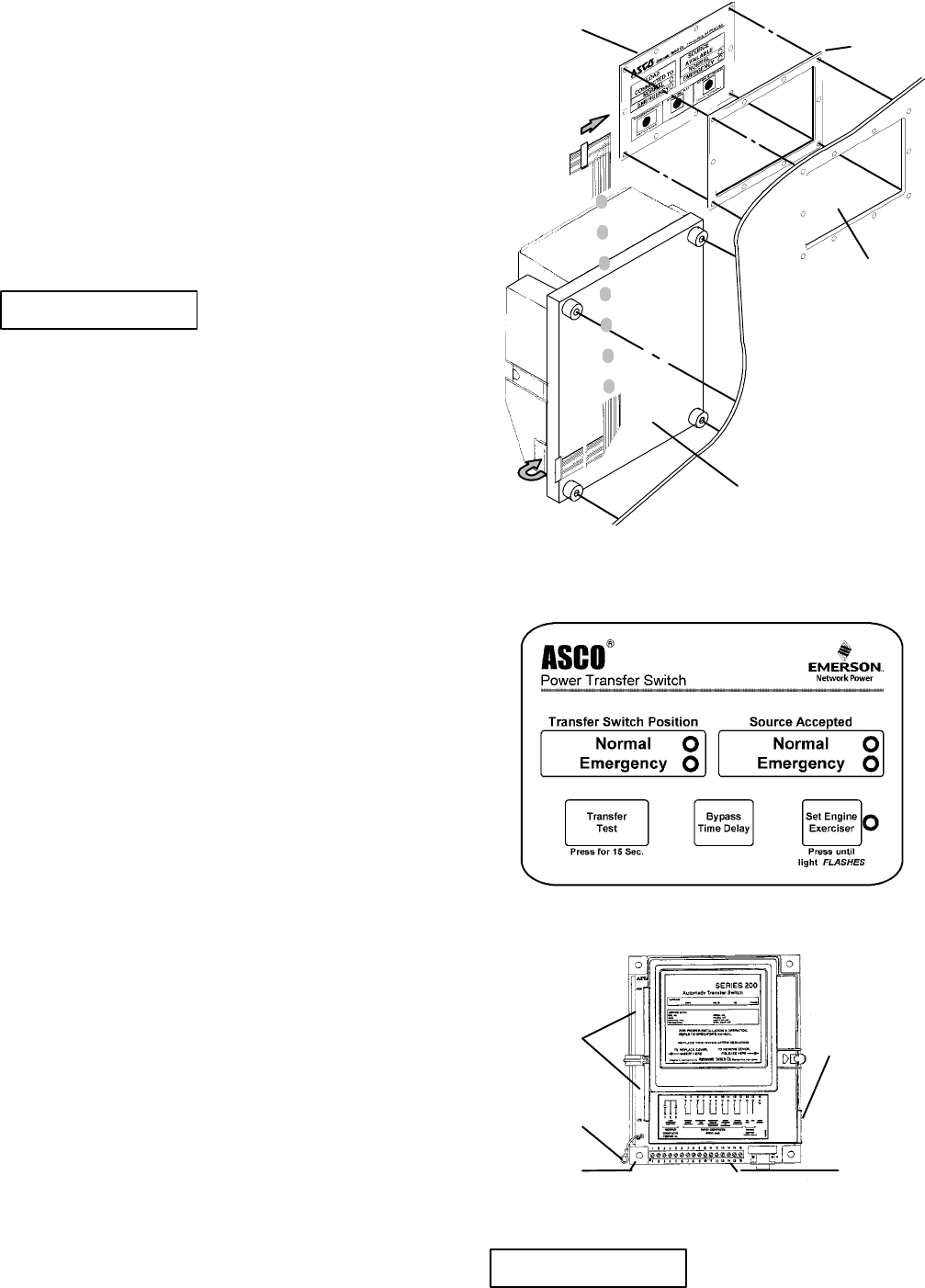
Mount the membrane controls and the controller on the
inside of the e nclosure door as shown on the Outline
and Mounting Diagram provided. The membrane
controls must be accessible through a cutout in the
door. Connect the membrane controls to the right side
of the controller with the ribbon cable provided. Then
connect the transfer switching device harness plugs to
the left side of the controller. See Figures 1–1 and 1–2.
An add-on rail is provided for some optional accesso-
ries. If provided, mounted it below the controller. Then
make the connections shown on the Wiring Diagram.
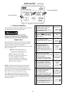
Grounding
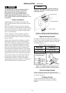
Grounding (earthing) is accomplished by mounting the
autom atic transfer switch ing equipment in a metal
enclosure. Connect the control panel grounding wire
(lower left side) to equipment (enclosure or clean earth)
ground. This wire can be connected to the controller’s
lower left mounting stud. Because the controller is
mounted on a door, a conductive strap must be used
between the enclosure and the door. This connection
provides proper grounding which does not rely upon the
door hinges. See Figure 1–3.
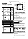
membrane
controls
ribbon
cable
controller
gasket
cut out in
enclosure
door
enclosure
door
controller
must be within a
steel enclosure
Figure 1-1. Membrane controls and controller mount-
ing on inside of enclosure door. Refer to
Outline & Mounting Diagram for mounting hardware.
Figure 1-2. Membrane controls with gasket
suitable for IP65 enclosure.
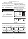
ribbon cable
to membrane
controls
ground
wire
mounting
stud
2 plugs for
transfer
switching
device
harness
connections
for control
features &
options
Figure 1-3. Controller grounding (clean earth)
wire and other connections.
NOTICE
The controller must be g rounded for proper
operation.