


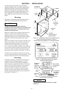

CONTROL FEATURES (continued)
5-- 4
INPHASE MONITOR
FOR MOTOR LOAD TRANSFER
Inphase monitori ng logic controls transfer and retransfer
of motor loads, so tha t inrush currents do not exceed
normal starting currents. It avoids nuisance tripping of
circuit breakers and mechanical damage to motor
couplings.
The Motor Load Transfer feature is built into the
controller. DIP switch S1 (actuator 5) activates this
feature: right = ON, left = OFF.
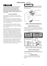
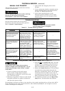
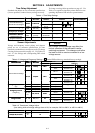
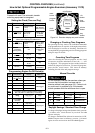
FUNCTION S1 DIP SWITCH
enable Actuator 5 on
5
disable Actuator 5 off
5
Shaded DIP switches are standard factory settings.
If the Motor Load Transfer feature is enabled,
it will be activated following
the Load
Disconnect Feature Delay Before Transfer
delay.
Note
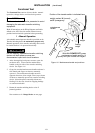
LOAD DISCONNECT FEATURE
Connect external circuits to the terminals indicated on
the Wiring Diagram provided with the ATSE.
The double throw (Form C) contact is rated for 28 VDC
or 120VAC (5 amps resistive). Thecontact operatesprior
to a selectable 0, 3, 10, or 20 second delay before transfer
of the automatic transfer switching device. The contact
resets either immediately following transfer or after the
same
delay as set for pre–signal before transfer.
Time delay between the load disconnect control signal
and initiation of transfer is set on the controller with DIP
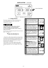
switch S2 (actuators 6, 7, 8) as shown below:
Delay Before Transfer
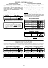
LD TDBT S2 DIP SWITCH
0 (disable)
Actuator 7 on
Actuator 8 on
87
3seconds
Actuator 7 on
Actuator 8 off
87
10 seconds
Actuator 7 off
Actuator 8 on
87
20 seconds
Actuator 7 off
Actuator 8 off
87
Shaded DIP switches are standard factory settings.
Delay After Transfer*
LD TDAT S2 DIP SWITCH
enable Actuator 6 on
6
disable Actuator 6 off
6
*Enabling the Delay After Transfer will cause the control
signal to reset after the same delay
as set for the Delay
Before Transfer.
REMOTE CONTROL FEATURES
These remote control features require a customer–supplied normally closed contact suitable for a 5 V dc low energy
circuit. Refer to the Wiring Diagram provided with the ATS. Activate appropriate DIP switch S2 actuators below.
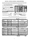
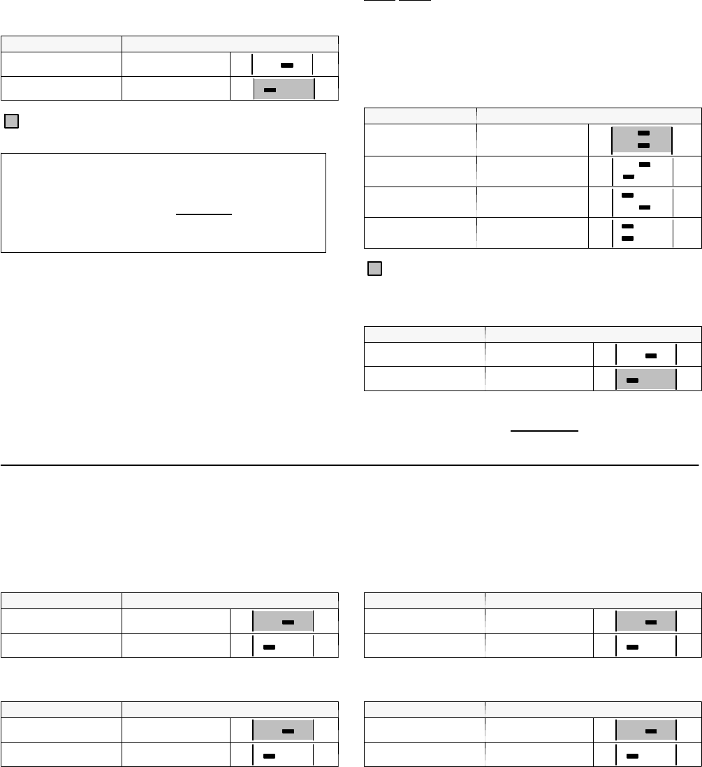
Remote Test (terminals CP6–7)
RTSW S2 DIP SWITCH
disable Actuator 3 on
3
enable Actuator 3 off
3
Bypass Transfer Time Delay (CP12–13)
TD E/N BYP. S2 DIP SWITCH
disable Actuator 1 on
1
enable Actuator 1 off
1
Remote Transfer to Eme rgency (CP8–9)
RT /E S2 DIP SWITCH
disable Actuator 2 on
2
enable Actuator 2 off
2
Inhibit Transfer to Emergency (CP10–11)
N/E INHIB. S2 DIP SWITCH
disable Actuator 4 on
4
enable Actuator 4 off
4