


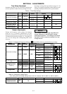
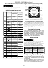

SECTION 4 ADJUSTMENTS
4-- 1
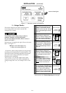
Time Delay Adjustment
Standard time delays are set to customer specifications
(if none specified, standard factory settings are used).
To change a setting, follow procedure on page 4-2. Use
Table 4-1 as a guide to time delay values and their corre-
sponding adjustment DIP switch or potentiometer.
Table4-1.TimeDelaySettings
DESCRIPTION LABELS
FACTORY
SETTING
ADJUSTMENT
RANGE
S3 DIP
SWITCH
ADJUSTMENT
POTENTIOMETER
Override Momentar
y
T
D
E
S
3
s
e
c
o
n
d
s
1second Actuator 1 on
1
O
v
e
r
r
i
d
e
M
o
m
e
n
t
a
r
y
Normal Source Outages
T
D
E
S
3secon
d
s
3seconds Actuator 1 off
1
—
T
r
a
n
s
f
e
r
t
o
E
m
e
r
g
e
n
c
y
TIMER 0 minutes 0to5
P
2
T
rans
f
er to
E
mergency
T
I
M
E
R
N
/
E
0
m
i
n
u
t
e
s
(full ccw)
0
t
o
5
minutes
—
—
P
2
Override Momentary
Emergency S. Outages
— 4seconds non-adjustable — — —
R
e
t
r
a
n
s
f
e
r
t
o
N
o
r
m
a
l
TIMER 30 minutes 1secondto
P
1
R
etrans
f
er to
N
orma
l
T
I
M
E
R
E
/
N
3
0
m
i
n
u
t
e
s
(full cw)
1
s
e
c
o
n
d
t
o
30 minutes
—
—
P
1
Unloaded Running
(Engine Cooldown)
— 5 minutes non-adjustable — — —
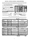
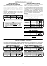
Sensor Adjustments
Voltage and f requency sensor pickup and dropout
points are set to customer specifications (if none
specified, standard factory settings are used). To change
a setting, follow procedure on page 4–2. Use Tables 4-2
and 4–3 for se ttings and corresponding DIP switch
actuators.
NOTICE
Any change in these settings may affect the
normal operation of the automatic transfer
switching equipment. This change could allow
the load circuits to remain connected to a low
voltage source.
Ta ble 4-2. Voltage and Frequency Settings. ( Shaded DIP switches are standard factory settings).
D
E
S
C
R
I
P
T
I
O
N
L
A
B
E
L
S
S
E
T
T
I
N
G
%ofnominal
S1 DIP
D
E
S
C
R
I
P
T
I
O
N
L
A
B
E
L
S
S
E
T
T
I
N
G
FACT . SET ADJ RANGE
S
1
D
I
P
SWITCH
P
U
/
N
P
i
c
k
u
p
9
0
%
95 % * Actuator 3 off
3
P
U
/
N
P
i
c
k
up 90 %
90 % Actuator 3 on
3
90 % *
Actuator 1 off
Actuator 2 off
21
Normal Source Voltage
D
O
/
N
D
r
o
p
o
u
t
8
5
%
85 %
Actuator 1 on
Actuator 2 off
21
DO
/
N Dropout
85 %
80 %
Actuator 1 off
Actuator 2 on
21
70 %
Actuator 1 on
Actuator 2 on
21
Emer
g
enc
y
Source Volt-
–– Pickup 90 % non-adjustable
E
m
e
r
g
e
n
c
y
S
o
u
r
c
e
V
o
l
t
age
–– Dropout 75 % non-adjustable
––
–– Pickup 95 % non-adjustable
E
m
e
r
g
e
n
c
y
S
o
u
r
c
e
–– Dropout 85 % non-adjustable
––
Emergency Source
Frequency
60
/
50
6
0
/
5
0
H
z
6
0
H
z
60 Hz Actuator 4 off
4
e
q
u
e
c
y
6
0
/
5
0
Hz
60
/
50
H
z 60
H
z
50 Hz Actuator 4 on
4
V
o
l
t
a
g
e
P
h
a
s
e
s
3
4
1
4
3
4
/
1
4
3
4
3phase Actuator 6 off
6
V
o
l
tage
P
h
ases 3 4 ,14 3 4
/
1 4 3 4
1phase Actuator 6 on
6
* If dropout voltage is set to 90%, the pickup voltage must be set to 95%.
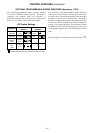
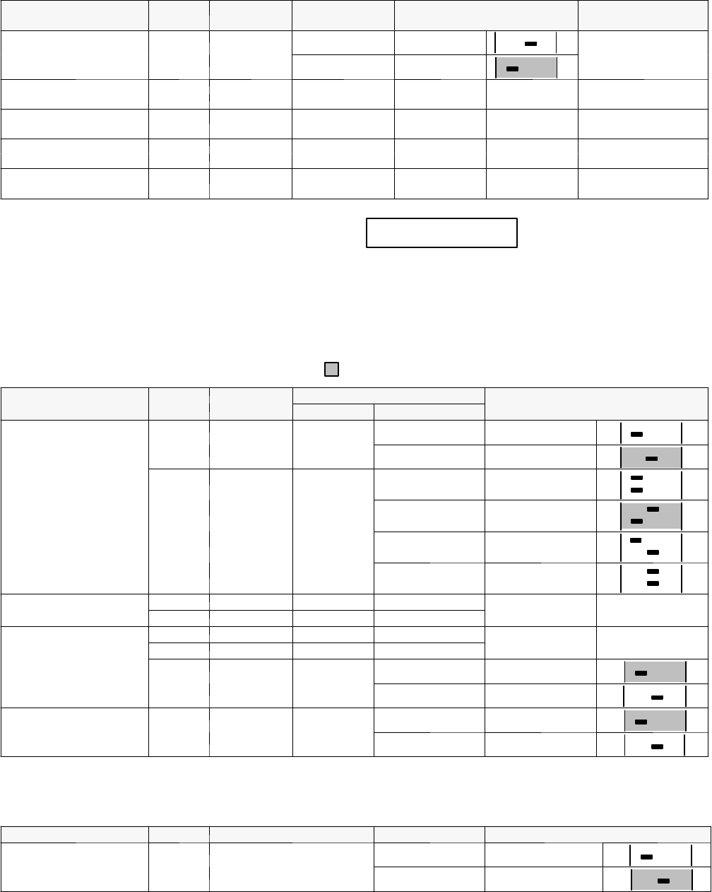
Table 4-3. Transformer Voltage Adjust.
(Low setting shifts all voltage settings down 4.2%; for example, 240 V to 230 V, or 480 V to 460 V)
DESCRIPTION LABELS FACTORY SETTING ADJUSTMENT S3 DIP SWITCH
V
o
l
t
a
g
e
A
d
j
u
s
t
(
4
2
%
)
L
OW
/
H
I
LOW Actuator 2 off
2
V
o
l
tage
A
d
j
ust
(
4.2%
)
L
O
W
/
HI
H
I
HI Actuator 2 on
2