


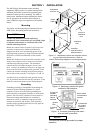
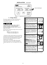
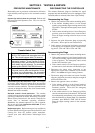
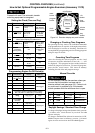
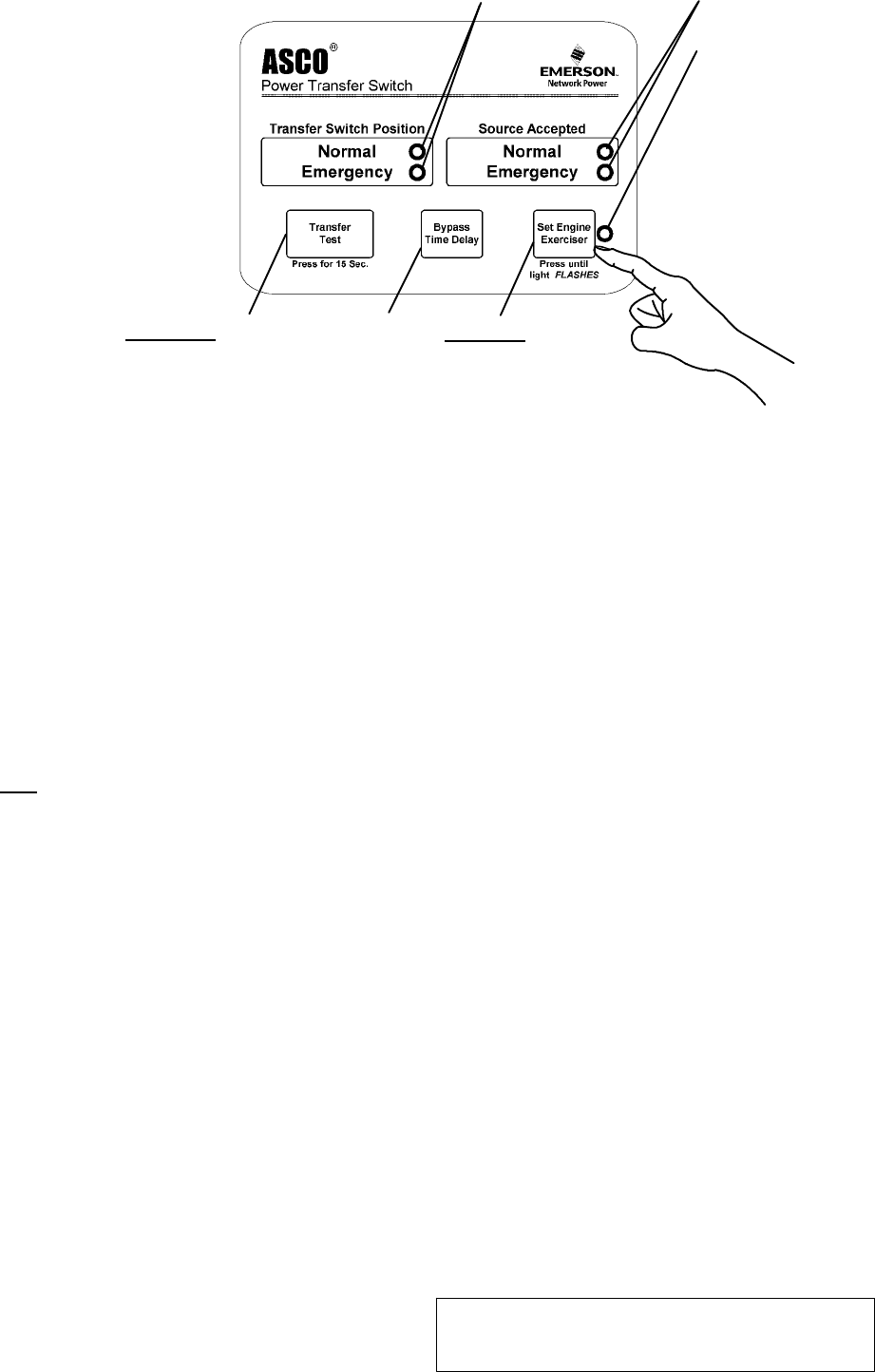
Hold 15 sec.to
start the engine
generator and t o
transfer the load
to emergency.
Press to cancel the
active exercise period
(stops engine now or
after cooldown) See
page 5–1.
Hold 5 sec
.toset
20 min. engine exercise
period immediately (engine
starts) and weekly thereafter.
³ blinks slowly when
button is released (set)
and during 20 min.
exercise period.
³ blinks rapidly when
button is held 5 sec.
while being set
Lights show position of transfer switching device.
Lights show the sources accepted.
Light for built–in
engine exercise timer:
Seepage5–1
for complete
instructions
Figure 2–1. Membrane controls and indicator lights.
³ stays on after engine
stops (exerciser is
enabled for weekly
operation)
SECTION 2 SEQUENCE OF OPERATION
2 --- 1
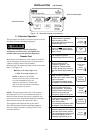
Transfer To Emergency
Thesequenceforloadtransferto
emergency source begins
automatically when normal
sou rce volta ge falls belo w t he
preset dropout point or when
Tra nsfe r Test b u tton is press ed. An
und er v oltag e c on d ition on any
phase of the normal source i s
detected by the senso r.
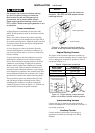
Whe n th e norma l
source voltage fails
or the Tra nsfe r Test
button is p r ess ed, the
SE relay de-ener-
gizes and relay NR
begins its timing
cycle (1 or 3 seconds,
momen t ar y no r mal
source outage de la y ) . The NR relay is prov ide d with a time
delay on dropout to override momentary outages and
prevent nuisance s tar ting o f t he en g ine-driven generator.
If the normal sourc e voltage returns above the sensor
dropou t setting befor e the time delay expires, the NR
relay timing cycle is reset to zero and relay SE energizes.
If the norm al sourc e vol tag e does not r eturn above the
sensor dropou t setting before the time del ay expires, the
NR r el ay d e-ener g izes a nd s ig nal s the en g ine-driven
gen erator to s tar t. At t h e same time, a voltag e and
frequenc y sen sor b eg ins m on itoring th e emergenc y
source. The sensor will accept the emergency source only
when both voltag e and frequency reach pres et pickup
points. Usually a bout t en sec onds el apse from dropout of
the NR rel ay to acc eptan c e b y the sensor . Th is time span
occurs because the engine-driven generator must crank,
start, and run up to nominal pickup points. For this
reason, if the Tr ansf e r Test buttonispresseditmustbe
held for 15 seconds. If the emergency source is available
imm ed iately, the sensor m ay acc ept it as soon as NR r el ay
drops out.
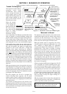
When the emergency source is accepted by the sensor,
relay ER begins its timing cycle (trans fer to emergency
delay). ER relay is provided with an adjustable (0 to 5
minutes) time delay on pickup to delay transfer of the
load to the emergency source. For immediate transfer
press Bypass Time Delay button.
ER relay energizes, the TS coil is energized, the
transfer switching device operates, and all switch
contacts (mains, controls, auxiliaries) reverse position.
The transfer switch is now supplying the load from the
emergency source.
The t ransfer switching de vice will remain i n the
Emergencypositionuntilthenormalsource isrestored.
If the Transfer Test button is used, the transfer switching
device will remain on emergency until the retransfer to
normal delay times out.
Retransfer to Normal
The sequence for load retransfer to the normal source
automatically begins when the voltage sensor detects
restoration o f the normal source. The voltage level
must rise above the preset pickup point on all phases
before the sensor will accept the normal source.
When the normal source is accepted by the sensor,
relay SE begins its timing cycle (adjustable 1 sec. to 30
min., retransfer to n o rmal delay). For immediate
retransfer press Bypass Time Delay button. SE relay i s
provided with a time delay on pickup to prevent
immediate load retransfer to the normal source. The
delay i nsures that the normal source has stabilized
before reconnection of vital loads. If the normal source
voltage falls below the present dropout point before the
time delay expires, the timing cycle i s reset to zero. If
the emergency source fails for more than 4 seconds
duringthe timingcycle, ERrelay drops out and the load
is immediately retransferred to the normal source, if
that source is acceptable.
SE relay energizes and ER relayis dropped out. The TS
coil is energized, the transfer switching device oper-
ates, and all switch contacts (mains, controls, auxilia-
ries) reverse position. T he transfer switching device is
now supplying the load from the normal source again.
Upon retransfer to the normal source, NR relay begins
its timing cycle (unloaded running delay [engine cool-
down] ). NR relay is provided with a 5 minute time
delay o n pickup to keep the engine running for a
cool-down period.
NR relay energizes after the time delay and signals the
engine-driven generator to shut down. All circuits are
reset for any future normal source failure.
Activation of standard control features shown in Section
5 will alter the sequence of operation and introduce
addition al time delays during transfer operations .