23
Installation
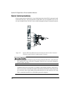
(ECI-44) which provides a convenient screw terminal connection strip. Connect one end of
the CMDX command cable to your drive and the other end to the ECI-44.
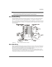
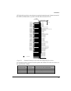
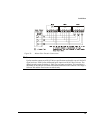
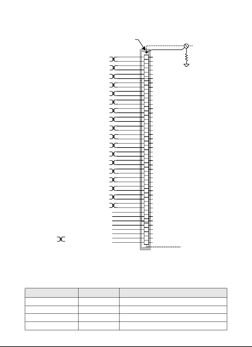
Figure 20: Command Connector (J5) Pinout and CMDO-XXX Wire Colors
For information about Command Connector pinout and CMDO-XXX cable wire colors, see
the “Specifications” chapter.
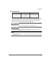
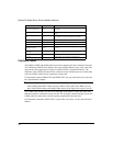
Function Pin Numbers Electrical Characteristics
Inputs and Drive Enable 1, 2, 3, 4, 16 10-30 V (“On”) 0-3 V (“Off”) optically isolated
Outputs 17, 18, 19 10-30 VDC sourcing 150 mA
I/O Supply 33, 34 10 - 30 VDC @ 1 Amp maximum
I/O Common 31, 32 I/O return
1
2
3
4
5
6
7
8
9
10
11
12
13
14
15
16
17
18
19
20
21
22
23
24
25
26
27
28
29
30
31
32
33
34
35
36
37
38
39
40
41
42
43
44
Input #1
Input #2
Input #3
Input #4
RS 485+
Encoder Output Channel A
Encoder Output Channel A/
Encoder Supply +5 Volts - Output. 200 mA
Encoder Common
Do Not Connect
Do Not Connect
Drive Enable Input
Output #3
Output #2
Output #1
RS 485-
Encoder Output Channel B
Encoder Output Channel B/
Diagnostic Output Common
I/O Common -
I/O Common -
I/O Supply +
I/O Supply +
Encoder Output Channel Z
Encoder Output Channel Z/
Diagnostics Output Channel 1
Diagnostics Output Channel 2
Command Connector
Do Not Connect
Do Not Connect
Do Not Connect
Do Not Connect
Do Not Connect
Do Not Connect
Do Not Connect
Do Not Connect
Shield
PE
10 Ohm
Connector Shell
Connected to
+15 Out (Test Only)
= Twisted Pair
Do Not Connect
Do Not Connect
Do Not Connect
Do Not Connect
Do Not Connect
Do Not Connect
Do Not Connect
Do Not Connect
(YEL/BRN)
(BRN/YEL)
(BRN/PRP)
(PRP/BRN)
(GRY/PRP)
(PRP/GRY)
(BLU/WHT)
(WHT/BLU)
(RED/WHT)
(WHT/RED)
(GRN/WHT)
(WHT/GRN)
(BLK/GRN)
(PRP/GRN)
(YEL/BLU)
(BLU/YEL)
(GRN/PRP)
(GRN/BLK)
(PRP/ORG)
(BLK/RED)
(RED/BLK)
(ORG/PRP)
(BLK/BRN)
(BRN/BLK)
(BLK/BLU)
(PRP/BLU)
(BLU/RED)
(RED/BLU)
(BLU/PRP)
(YEL/ORG)
(ORG/YEL)
(BLU/BLK)
(BRN/RED)
(RED/BRN)
(GRY/YEL)
(YEL/GRY)


