


19
Installation
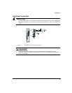
Note
The motor ground wire and shields must be run all the way back to the amplifier terminal
and must not be connected to any other conductor, shield or ground.
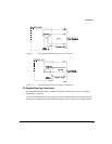
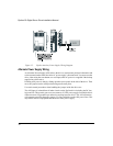
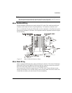
Motor Feedback Wiring
Encoder feedback connections are made with the CFCS cable. This cable has an MS style
connector on the motor end and a 26-pin high density “D” connector on the drive end.
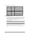
For A, A, B, B and Z, Z pairs, the CFCS cable uses low capacitance (~10 pf/ft) wire to get a
characteristic impedance of 120 ohms. This impedance match is important to minimize signal
loss and ringing.
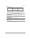
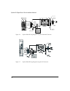
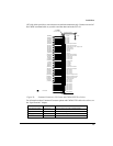
Figure 15: Motor Feedback Connector Pinout
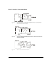
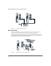
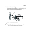
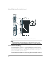
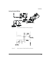
Motor Brake Wiring
Motors equipped with brakes have a three-pin MS style connector. The Control Techniques
brake power cable (model CBMS-XXX) has an MS style connector on the motor end and
three wire leads on the amplifier end (see wiring diagram below).
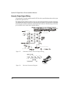
You must provide a DC power supply rated at +24 VDC with a 2 amp minimum current
capacity for the brake. If you use this voltage source to power other accessories such as I/O
or more than one brake, you must increase its current capability.