


System Application Guide SAG582135000
Spec. No. 582135000 (Model LXP48F1) Issue AE, January 31, 2007
Page 19 of 43
This document is property of Emerson Network Power, Energy Systems, North America, Inc. and contains confidential and proprietary information owned by Emerson Network Power, Energy
Systems, North America, Inc. Any copying, use, or disclosure of it without the written permission of Emerson Network Power, Energy Systems, North America, Inc. is strictly prohibited.
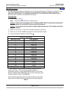
TPS/TLS-Type Fuses
A single fuseholder provides for installation of a 3 to 100 ampere Bussmann TPS-type or Littelfuse TLS-type
fuse. This fuseholder plugs into a single mounting position on the compatible distribution bus options
described in this document. This fuseholder provides a GMT-A alarm type fuse, which operates open to
provide an alarm indication if the distribution fuse opens.
Ordering Notes
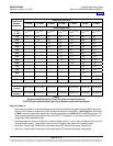
1) Order fuses per Table 2
.
Note: Load should not exceed 80% of device rating.
Caution:
A fuse with a rating greater than 75 amperes SHALL HAVE an empty mounting position
between it and any other overcurrent protective device.
Caution:
The maximum size fuse used in ambient temperatures above +50°C ambient shall be 40
amperes.
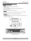
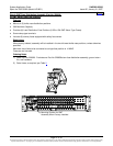
2) Order one (1) Part No. 117201 TPS/TLS-type fuseholder for each fuse.
3) Order one (1) Part No. 524690 mounting kit for each fuseholder ordered.
4) For lug and wire size selection, refer to Table 4
.
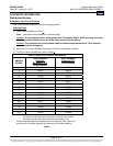
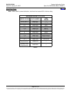
TPS/TLS-TYPE FUSES
AMPERE RATING PART NUMBER
3 248230900
5 248231000
6 248231200
10 248231500
15 248231800
20 248232100
25 248232400
30 248232700
40 248233300
50 248233900
60 248234200
70 248234500
80 118413
90 118414
100 118415
TPS/TLS-Type Fuseholder* 117201
* Fuseholders are not furnished and must be ordered as required.
Order (1) Part No. 117201 for each fuse position required.
Fuseholder includes (1) alarm fuse (Bussmann GMT-A 18/100 amp;
Emerson Network Power 248610301) and (1) alarm fuse safety cover
(Emerson Network Power P/N 248898700).
Unless otherwise specified, fuses are to be mounted from right to left
starting with the highest capacity and working to the lowest capacity.
Table 2
Home