


SAG582135000 System Application Guide
Issue AE, January 31, 2007 Spec. No. 582135000 (Model LXP48F1)
Page 36 of 43
This document is property of Emerson Network Power, Energy Systems, North America, Inc. and contains confidential and proprietary information owned by Emerson Network Power, Energy
Systems, North America, Inc. Any copying, use, or disclosure of it without the written permission of Emerson Network Power, Energy Systems, North America, Inc. is strictly prohibited.
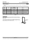
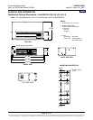
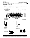
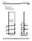
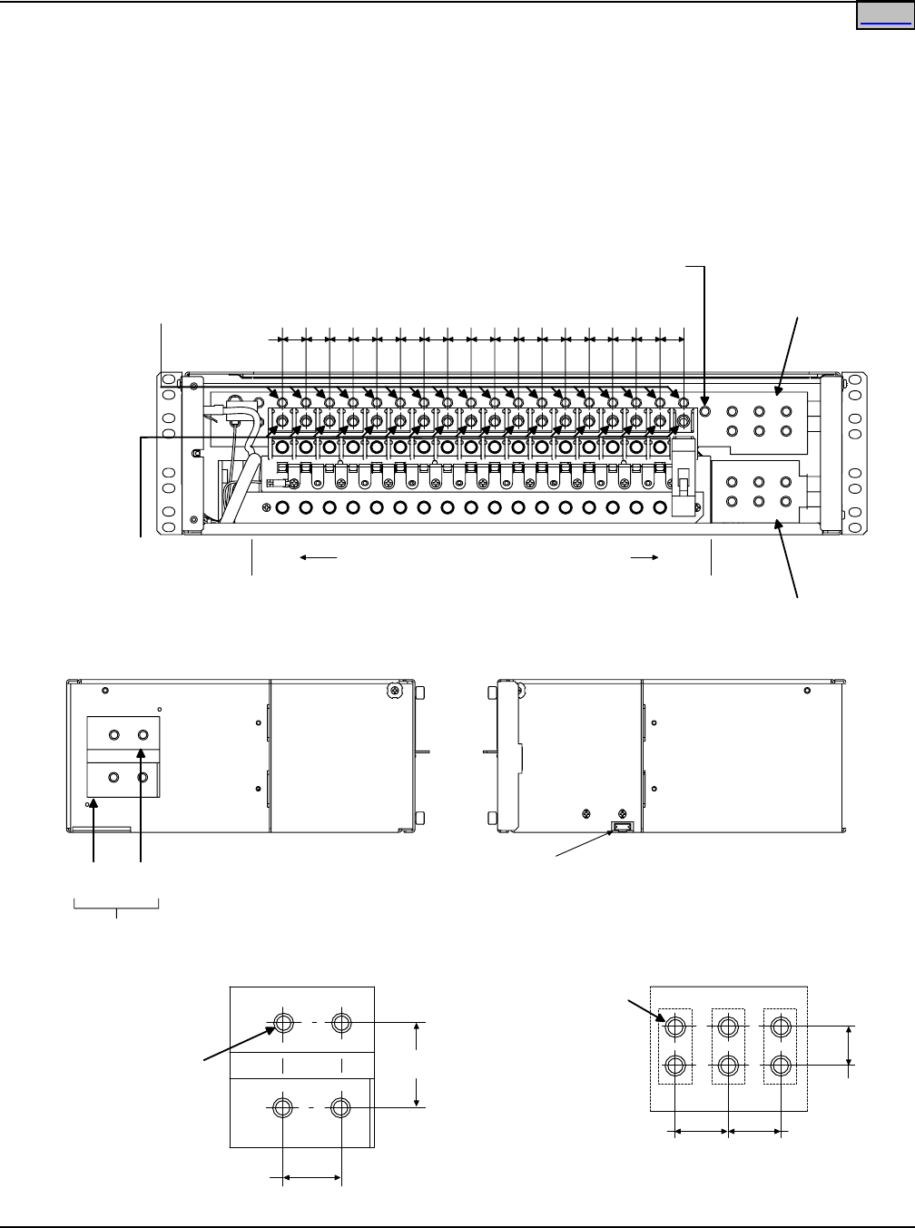
Distribution Cabinet Electrical Connection Locations and Dimensions—
Lists BD, BL, BS, LB, LD, LS, LX
Notes:
1. For electrical connection locations and dimensions of List 1 Power Shelves, refer to SAG589200100.
2. All dimensions are in inches.
3. Distribution and battery cabling to exit cabinet through top panel.
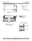
0.875
0.625
0.875
DETAIL B
1/4-20 Captive Nut
6 Places
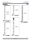
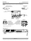
LEFT SIDE VIEW
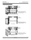
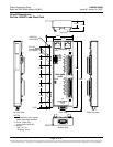
NEG
(-)
POS
(+)
INPUT FROM
POWER SHELF
See Detail A
RIGHT SIDE VIEW
J10
MCA
Control
Bus
FRONT VIEW
(COVER REMOVED)
0.765
POS. (+) BATTERY
LUG LANDINGS
See Detail B
NEG. (-) BATTERY
LUG LANDINGS
See Detail B
LOAD RETURN
CONNECTIONS
1/4-20 Captive Nut, 36 Places,
for 2-Hole Lugs on 5/8" Centers
(Factory Supplies Lug
Mounting Hardware)
LOAD
CONNECTIONS
1/4-20 Threaded Hole,
18 Places, for 1-Hole Lugs
(Factory Supplies Lug
Mounting Hardware)
Central Office Ground
(1/4-20 Captive Nut)
LOAD FUSES or CIRCUIT BREAKERS
F1/
CB1
F18/
CB18
DETAIL A
1.406
1.000
1/4-20 Captive Nut
2 Places Per Polarity
Home