


SAG582135000 System Application Guide
Issue AE, January 31, 2007 Spec. No. 582135000 (Model LXP48F1)
Page 28 of 43
This document is property of Emerson Network Power, Energy Systems, North America, Inc. and contains confidential and proprietary information owned by Emerson Network Power, Energy
Systems, North America, Inc. Any copying, use, or disclosure of it without the written permission of Emerson Network Power, Energy Systems, North America, Inc. is strictly prohibited.
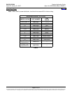
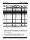
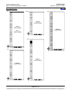
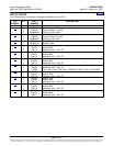
Relay Rack Options
The Power System is factory mounted to the relay rack specified when ordered. The following relay racks are
available:
Part
Number
Size
Available
Mounting Positions
(1U = 1-3/4”)
Notes
525004 51-3/8”H x 23”W 28U Welded
524915 6’0”H x 23”W 38U Welded
524913 7’0”H x 23”W 45U Welded
525111 7’0”H x 23”W 45U
Seismic (complies with
Bellcore Seismic Zone 4 requirements)
524914 7’6”H x 23”W 48U Welded
534821 8’0”H x 23”W 51U Welded
Table 6
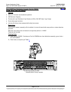
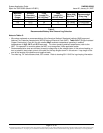
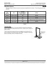
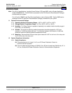
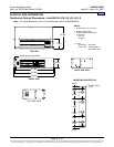
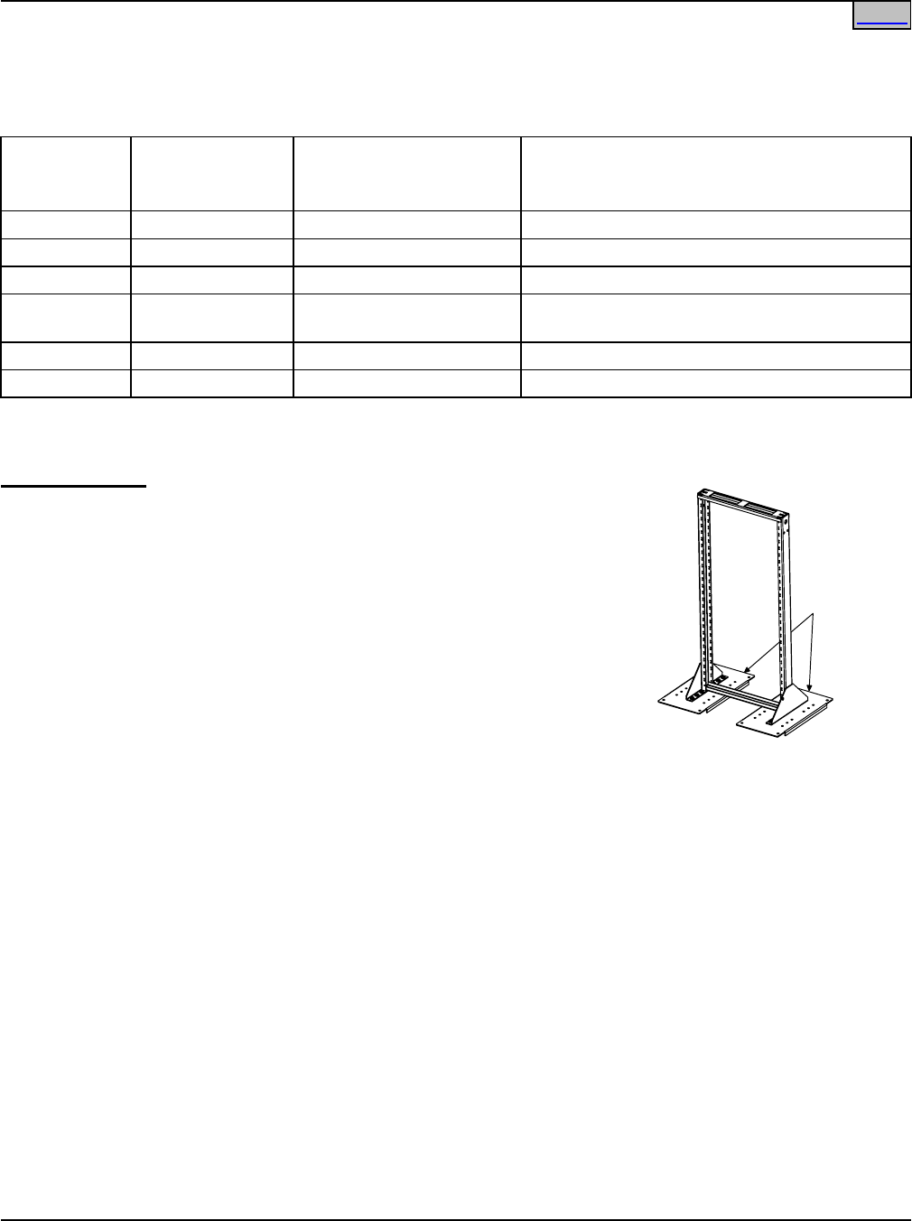
Transition Plates
Order Part No. 509819 for a Transition Plate Kit to mount relay racks above
battery modules with outside dimensions of 26.75" x 26.38", 35.75" x 26.38", or
42.50" x 26.38".
The kit consists of two plates with three hole patterns and hardware (3/8") to
mount the plates to the following relay racks: 525004. Hardware to mount the
plates to the battery module is customer provided.
Home
TRANSITION
PLATES