


System Application Guide SAG582135000
Spec. No. 582135000 (Model LXP48F1) Issue AE, January 31, 2007
Page 23 of 43
This document is property of Emerson Network Power, Energy Systems, North America, Inc. and contains confidential and proprietary information owned by Emerson Network Power, Energy
Systems, North America, Inc. Any copying, use, or disclosure of it without the written permission of Emerson Network Power, Energy Systems, North America, Inc. is strictly prohibited.
Recommended Wired Size and Lugs
Distribution (Load) Wire Sizes and Lugs—List BD, BL, BS, LB, LD, LS, LX
Features
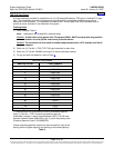
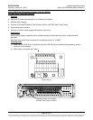
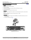
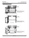
♦ In each Distribution Cabinet, lug-terminated load conductors are connected to the distribution fuseholder or
circuit breaker mounting positions and the ground busbar. The distribution fuseholder or circuit breaker
mounting positions provide 1/4-20 threaded holes for installation of customer-provided one-hole lugs that
have 1/4 in. bolt clearance holes. The ground busbar provides 1/4-20 threaded holes for installation of
customer-provided two-hole lugs that have 1/4 in. bolt clearance holes on 5/8” centers. Factory provides lug-
mounting hardware for the distribution fuseholder or circuit breaker positions and distribution ground busbar.
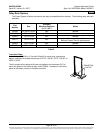
♦ For lug mounting hole size and spacing dimensions, refer to Electrical Connection Locations and Dimensions
under Physical Size Information in this document. Maximum size of wire to be connected to a single
fuseholder or circuit breaker position is 2 AWG.
Restrictions
All lugs for customer connections must be ordered separately.
Ordering Notes
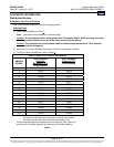
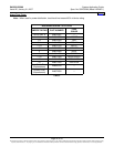
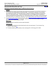
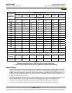
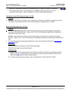
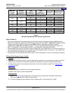
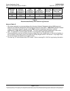
1) The rating of the distribution device determines the wire size requirements. For wire size and lug
selection, refer to Table 4
.
2) For other available lugs and hardware, refer to drawings 031110100 through 031110300.
Home