


SAG582135000 System Application Guide
Issue AE, January 31, 2007 Spec. No. 582135000 (Model LXP48F1)
Page 26 of 43
This document is property of Emerson Network Power, Energy Systems, North America, Inc. and contains confidential and proprietary information owned by Emerson Network Power, Energy
Systems, North America, Inc. Any copying, use, or disclosure of it without the written permission of Emerson Network Power, Energy Systems, North America, Inc. is strictly prohibited.
Maximum
Current
(Amps)
Ambient
Operating
Temperature
(1)
Loop
Length (Ft)
1.0 Volt Drop
(2)
Loop
Length (Ft)
0.25 Volt Drop
(2)
Recm 90°C
Wire Size
(1)
Recommended
Crimp Lug
(3)
List BB, BD, BL, BS, LB, LD, LS, LX
37 9 (3) 4 AWG (3) 245346800
500 40°C
59 14 (3) 2 AWG (3) 245350800
37 9 (3) 4 AWG (3) 245346800
500 50°C
59 14 (3) 2 AWG (3) 245350800
400 65°C 59 14 (3) 2 AWG (3) 245350800
List GA
163 40°C 36 9 (1) 2 AWG (1) 245350800
155 50°C 38 9 (1) 2 AWG (1) 245350800
110 65°C 54 13 (1) 2 AWG (1) 245350800
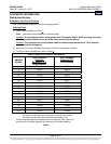
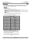
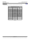
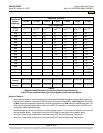
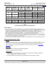
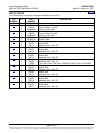
Table 5
Recommended Battery Wire Size and Lug Selection
Notes to Tables 5:
1
Wire sizes are based on recommendations of the American National Standards Institute (ANSI) approved
National Fire Protection Association's (NFPA) National Electrical Code (NEC). Table 310-17 (Single-Insulated
Copper Conductors in Free Air) for wire rated at 90°C conductor temperature operating in ambient
temperatures of 40°C, 50°C and 65°C was used. For other operating ambient temperatures, refer to the
NEC. For operation in countries where the NEC is not recognized, follow applicable codes.
2
Recommended wire sizes are sufficient to restrict voltage drop to the voltage shown in the column heading, or
less, at rated full load output current of the shelf for the loop lengths shown in this column. Loop length is the
sum of the lengths of the positive and negative leads.
3
Two-hole lug, 1/4" bolt clearance hole, 5/8" centers. Refer to drawing 031110100 for lug crimping information.
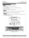
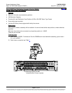
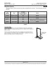
DC Input Wire Sizes and Lugs—List GA
Features
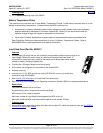
♦ In the List GA Distribution Cabinet, lug-terminated battery conductors are connected to the battery terminals.
Captive nuts, (1/4-20 on 5/8" centers) are provided for installation of customer provided two-hole lugs.
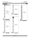
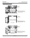
♦ For lug mounting hole size and spacing dimensions, refer to the illustration provided in the Physical Size
Information section.
Restrictions
All lugs for customer connections must be ordered separately.
Customer must supply lug-mounting hardware.
Ordering Notes
1) Refer to Table 5
for recommended wire sizes and lugs at rated maximum Distribution Cabinet load.
When making connections, observe correct polarity.
2) For other available lugs and hardware, refer to drawings 031110100 through 031110300.
Home