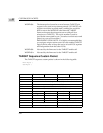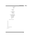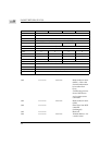
TARGET Sequence Custom Packet
2-27
2
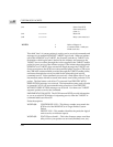
(Byte 01): Not used by the TARGET role firmware. Must be set to $00.
CT words $02 and $04: LINK POINTER. Not used by the TARGET role
firmware.
CT word $06: COMMAND LENGTH. Not used by the TARGET sequence call.
(The CDB received from initiator is stored in the command table that was
provided in the TARGET enable call. You may use the same command tables
for the enable and sequence calls to interpret receive CDB, but the TARGET
sequence call does not make use of the command length and of the CDB itself.)
CT words $08 through $12: COMMAND DESCRIPTOR BLOCK. Not used by
the TARGET sequence call. (Refer to CT word 06 above for command length.)
CT word $14, even byte: User SCSI STATUS. For a TARGET sequence, you can
set the vendor unique bits in the status byte. The MVME147 SCSI firmware
sends the contents of this byte ORed with the firmware SCSI status byte in
offset $64 if a status phase code is encountered in the TARGET script. (Odd
byte $15: initiator SCSI address which is interfacing with the TARGET role
firmware.)
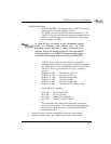
D7 = Not used by the TARGET role firmware. (This is the link bit.
Command linking is not accomplished with the use of this
bit.)
D6 = Not used by the TARGET role firmware. (This is the parity
bit. )
D5 = Not used by the TARGET role firmware. (This is the DMA
disables bit. DMA is used in TARGET role: 0 = DMA, 1 = no
DMA)
D4 = MUST be zero. Not used by the TARGET role firmware. (This
is the interpret bit and only relevant for initiator role.)
D3 = Not used by the TARGET role firmware. (This is the
SASI/SCSI rule bit. The TARGET role module determines
which rule to follow by the initiator assertion of ATN and the
re-select option bit of the IDENTIFY message.)
D2 = This is a scatter/gather bit. If DMA is enabled, the data
pointer in the command table could be used to point to the
scatter/gather table if this bit is 1.
D1 = 1 = SYNC transfer enable.
0 =ASYNC transfer enable.
D0 = Reserved.


