


5
WRITING A DRIVER
Introduction
This chapter covers information essential in writing a driver to support the
SCSI interface in interrupt mode. A driver for non-interrupt mode is a trivial
subset of the interrupt mode driver. The approach taken is to describe the
major sections of a driver that need to be written. The examples shown have
been extracted from the VERSAdos SCSI driver, and are dependent on the
driver interface to the VERSAdos operating system. For this interface, see
Figure 5-1. For details of the interaction between the driver and the SCSI
firmware, see Figure 5-2.
Any driver that communicates to the SCSI firmware starts by building (for
single callers) a command packet in memory and calling the command entry
point SCSI_CMD in the MVME147Bug. The address of the packet is
contained in register A2.
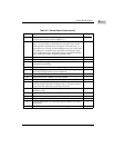
Access to the six SCSI entry points is provided through the use of a jump table
located within the beginning of the MVME147 debug monitor. The jump table
entry points and their SCSI firmware functions are shown in the following list.
Interrupts from the SCSI controller chip are through vector $45 (offset $114).
Interrupts from the MVME147 SCSI DMA channel are through vector $46
(offset $118). The self interrupts from the MVME147 SCSI firmware use the
vector $4B (offset $12C) to return control to SCSI firmware. The SCSI firmware
sets these vectors to point to its interrupt entry point.
SCSI_CMD
EQU $FFFE077C SCSI command entry.
SCSI_ACTV
EQU $FFFE0782 SCSI command
reactivation entry.
SCSI_INT
EQU $FFFE0788 SCSI interrupt entry.
SCSI_FUN
EQU $FFFE078E FUNNEL command
entry.
SCSI_CA
EQU $FFFE0794 Come-again entry.
SCSI_RTE
EQU $FFFE079A RTE entry.