Enabling TARGET Role
6-5
6
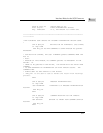
enable (word $0E = $C000), and with the following data structures
reserved for TARGET role service.
a. Command Table (384 bytes)
Note
During the TARGET role, when the TARGET enable packet
is issued to the firmware, neither the custom command
packet nor the command table shall be deallocated because
firmware uses both areas for subsequent TARGET service.
b. Message-out area (the SCSI standard allows for a 258-byte extended
message)
Note
In SCSI terms, all transfer directions are referenced to the
initiator. For example, the data out phase is a data phase for
data OUT of the initiator and INTO the TARGET.
Therefore, the message-out area mentioned above is for
message STORAGE from the initiator to the TARGET.
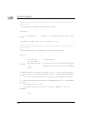
c. Take over the return vector specified in the packet of 1. above. Put the
service routine address in the vector.
d. Load address register A2 with the address of the custom sequence packet
described in 1. above.
e. Enter the SCSI firmware through the FUNNEL entry point ($FFFE078E) at
interrupt level 2. (For a description of the FUNNEL module, refer to the
SCSI Firmware Entry Points section in Chapter 1.
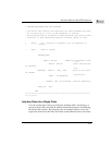
f. Examine the returned final status for a code of $xx17. This is a signal that
the firmware has acknowledged the enable packet and the initiator
command has been received. (This status may be preceded by a $A002 if
the bus is occupied at the time that the enable packet was sent to the
firmware.)
g. The service of the TARGET LUN is now interrupt-driven by the initiator.
A selection interrupt causes the firmware to examine enabled TARGET
LUNs and load commands and/or messages into the designated areas for
service. If a command is received for an enabled TARGET logical unit,
then the firmware returns to you with either a $xx17 final status (SCSI
mode) or an intermediate status of $xx06 (SASI mode or initiator not
supporting disconnection), indicating that the CDB has been loaded into


