


SCSI PACKETS
7-6
7
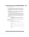
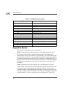
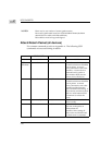
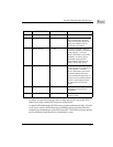
Old Packet Supported for Compatibility
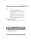
Even Byte \
Odd Byte \
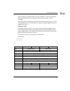
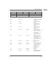
NOTE
S:
1. Refer to Chapter 3.
2. Refer to the following scatter/gather table format.
3. The interrupt level of this firmware can be from level 0 to 7. It should be
kept the same throughout the firmware execution; i.e., when the user has
chosen a specific interrupt level, it must not be changed until there is no
outstanding command.
4. The return vector should point to the user return routine at all times for
the proper return path.
5. Because both the interrupt vector and the return vector use the Vector
Base Register (VBR) to locate the proper address to resume the operation,
the VBR should not be changed if there are any outstanding SCSI
commands.
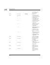
6. During scatter/gather operation, no automatic RETRY is performed by
SCSI firmware and the scatter/gather table contents could be modified by
the firmware when the command is completed.
7. For tape, if the previous tape attach had both physical bytes per block and
logical bytes per block = 0 (variable block size). This field is number of
bytes to transfer.
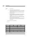
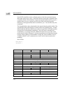
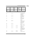
FC B8 74 30
+$00 Controller LUN Device LUN
+$02 Status Byte 0 Status Byte 1 (Note 1)
+$04 Memory Address (MSW) (Note 2)
+$06 Memory Address (LSW) (Note 2)
+$08 Sector Number (MSW)
+$0A Sector Number (LSW)
+$0C Number of Sectors to Transfer
+$0E 0000
+$10 Scatter/Gather Count