


Electrical Connections
31
7.0 ELECTRICAL CONNECTIONS
Power is supplied to the XDF through two factory-connected power cords (120V and 208V). For more
information, refer to 4.5.1 - Voltage Input Requirements
Additional electrical connections required for operation depend on the equipment installed in the
XDF and remote communications desired.
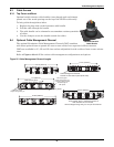
The XDF has slots for two communication cards, such as Liebert’s Intellislot card, and two
alarm/warning hardwire connections. These connections are at the top left corner of the self-con-
tained, air cooled XDF, inside the area housing the condenser coil (see Figure 21). For details, see
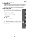
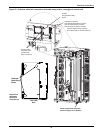
10.1 - Environmental Control. Water cooled XDF units have the connections on the top of the unit,
near the middle of the compartment (see Figure 22).
Alarm and warning contacts may be connected to monitoring equipment, such as Liebert’s Universal
Monitor and SiteLink equipment, as well as to building management systems. Consult the monitor-
ing equipment’s user manual for details.
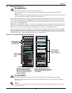
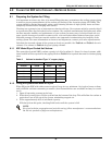
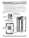
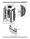
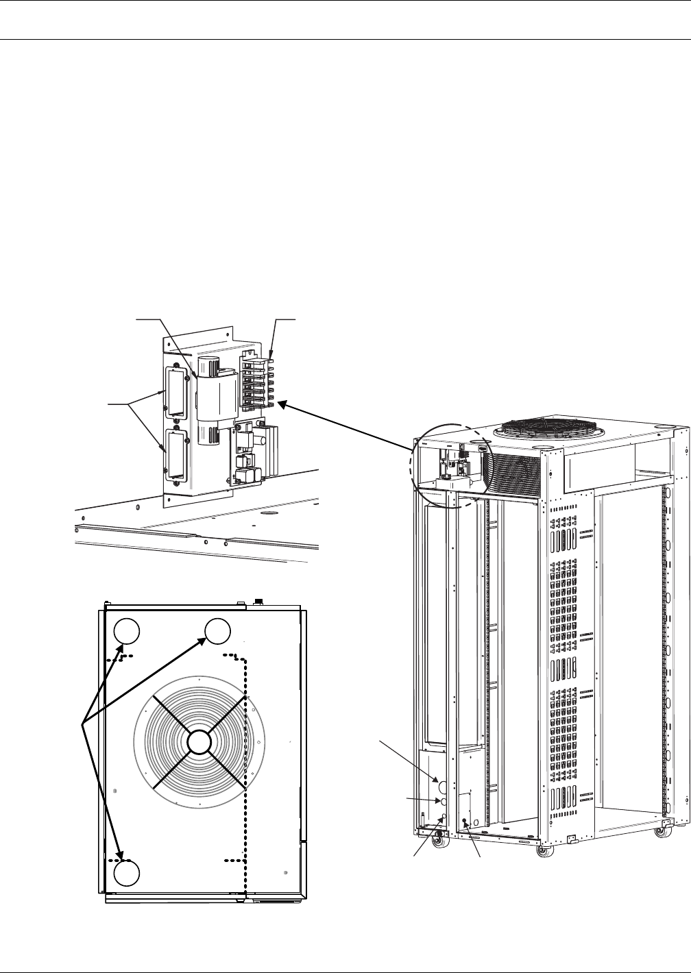
Figure 21 Customer electrical connections and cable entry points—self-contained, air cooled units
Customer
Cable Entry
Points
A
mbient
Temperature/Humidity
Sensor
Customer Connections:
75 & 76 Customer Alarm Contacts
94 & 95 Customer Warning Contacts
37 & 38 Remote Shutdown Contacts
(all contacts rated 1A, 24VAC maximum)
Communication
Card Slots (cards
provided when
option is selected)
Detail Area
LEFT SIDE of XDF
REAR of XDF
Service
Gauge
Access
Three-Phase Power
Cord Entrance
Single-Phase Power
Cord Entrance
Move plate to back panel
for alternate power cable routing
Dashed line delineates
equipment compartment