


Electrical Connections
32
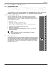
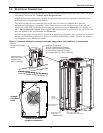
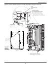
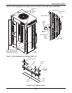
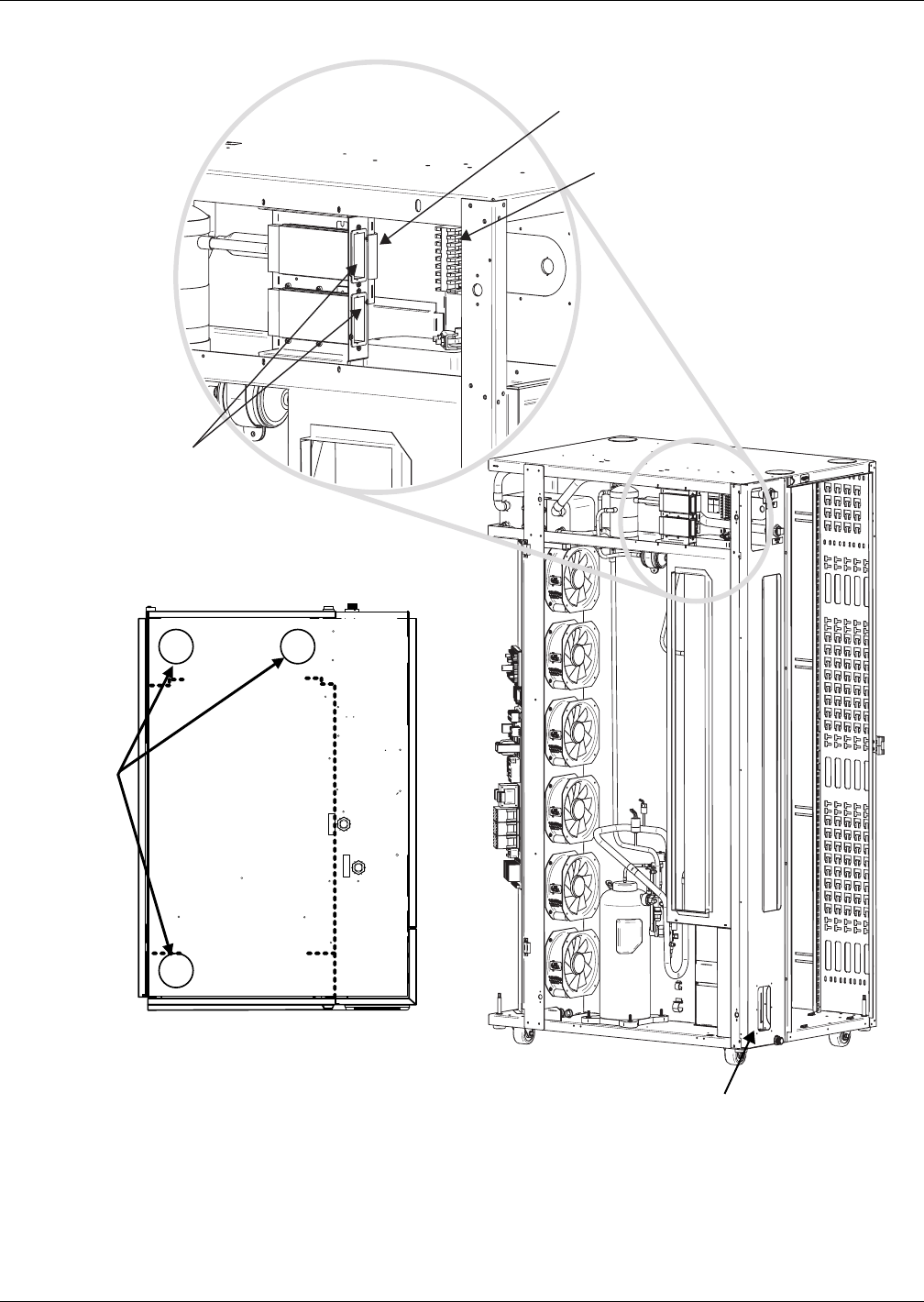
Figure 22 Customer electrical connections and cable entry points—water/glycol cooled units
Move plate to back panel for alternate
power cord routing (see also Figure 23)
Customer Connections:
37 & 38 Remote Shutdown Contacts
75 & 76 Customer Alarm Contacts
94 & 95 Customer Warning Contacts
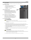
Ambient
Temperature/Humidity
Sensor
Communication
Card Slots (cards
provided when
option is selected)
(Contacts listed from top to bottom;
All contacts rated 1A, 24VAC maximum)
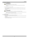
RET URN
(OUT)
SUPPLY
(IN)
Customer
Cable Entry
Points
TOP VIEW
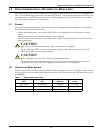
Rear
Dashed line
delineates
equipment
compartment
Power connection locations
(refer to Figure 21 for details)