


Electrical Connections
33
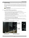
7.1 Utility Power Supply
The XDF’s 120V and 208V input power cords are stored for shipment in a compartment at the bottom
left of the rear of the XDF. The 10 feet (3m) cords may be routed to power outlets on the floor or wall.
If the power connections are overhead, the cables may be routed inside the unit and out the top. Lie-
bert recommends pulling the cables across the floor of the rack-mounted equipment compartment and
up the right rear side. This permits securing cables to the cable management cutouts along the inside
of the XDF.
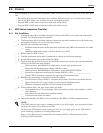
7.1.1 Route Input Power Cables Through the XDF’s Top
To route the factory-supplied input power cables inside the unit and out the top:
1. Open the rear door, revealing the back of the rack-mount equipment compartment.
2. Remove the six Phillips screws securing the small metal plate at the bottom left (inside the rack-
mount equipment compartment; see Figures 21 and 23).
3. Remove the cable entry snap bushing at the top right side of the rack-mount equipment
compartment to access the condenser coil compartment.
4. Remove the cable entry snap bushing from the top of the XDF.
5. Attach an optional cable bundle to the top of the panel that separates the rack-mount equipment
compartment from the condenser compartment.
6. Feed the input power cords through the opening at the bottom of the XDF and route them through
the optional cable bundle and out the top (see Figure 23).
7. Secure the cable bundle seal around the input power cords.
8. Secure the input power cables to the side of the XDF with optional Velcro ties or cable rings.
9. Install the small plate removed in Step 2 on the back of the XDF just above the condensate drain
(see Figure 23).
10. Connect the input power cables to appropriate utility supplies.
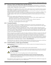
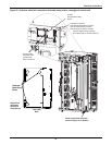
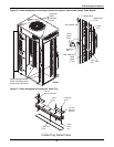
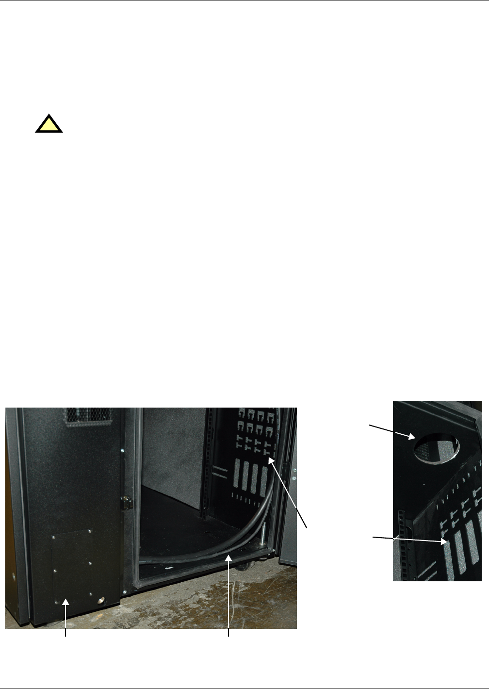
Figure 23 Route input power cords through XDF top
!
WARNING
Before beginning any work inside the XDF, disconnect all power inputs to the XDF and
installed equipment.
Route input power cables across
bottom of XDF to right rear side
Plate moved from inside
rack-mount equipment area
Attach optional
cable bundle to
upper side of
cable entry cutout
Secure input
power cables
to side panel