Enfora Enabler II-G Assisted GPS
Modem Integration Guide
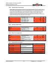
6.6.8. General Purpose Input/Output
Seven general-purpose input/output signals are provided along with one fixed output. Each of
these signals may be selected as inputs or outputs except GPIO-5, which is an output pin only.
They may be used independently as a user-specified function, or may be used to provide
modem control and status signals. Several examples of modem control signals are: power
shutdown command, register/deregister on network command, and transmitter disable.
Several examples of modem status signals are: registration status and ready-for-power-down
status to be used with power shutdown command signal.
I/O Lines Parameter/Conditions MIN TYP MAX UNIT
V
IL
Input Voltage – Low
-0.5 0.9 Vdc
V
IH
Input Voltage – High
2.0 3.4 Vdc
V
OL
Output Voltage – Low
0.64 Vdc
V
OH
Output Voltage – High
2.4 3.0 Vdc
I
IL
/ I
IH
Input Leakage Current
-1 1 μA
I
OL
/ I
OH
Rated Output Current
2 mA
6.6.9. Analog-To-Digital Input
Analog-To-Digital Input Parameter/Conditions MIN TYP MAX UNIT
ADC
BRES
ADC Binary Resolution
10 Bits
ADC
REF
ADC Reference Voltage
1.75 Vdc
V
ADC
ADC Range
0 1.75 Vdc
Z
ADC
ADC Input Impedance
100 kΩ
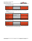
6.6.10. Digital-To-Analog Output
Digital-To-Analog Output Parameter/Conditions MIN TYP MAX UNIT
DAC
BRES
DAC Binary Resolution
10 Bits
T
S
Settling Time
10 μS
V
OMAX
Output Voltage with Code
Maximum
2.0 2.2 2.4 Vdc
V
OMIN
Output Voltage with Code
Minimum
0.18 0.24 0.3 Vdc
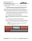
6.6.11. Handset Microphone Input
Parameter Conditions MIN TYP MAX UNIT
Maximum Input Range –
Mic(+) to Mic(-)
Inputs 3 dBm0 (Max. digital
sample amplitude when PGA
gain set to 0 dB)
32.5 mVrms
Nominal Ref. Level –
Mic(+) to Mic(-)
-10 dBm0
Differential Input Resistance –
Mic(+) to Mic(-)
100 kΩ
Microphone Pre-Amplifier Gain 25.6 dB
Bias Voltage on Mic(+)
2.0 or 2.5 V
2.0 2.5 Vdc
Mic Bias Current Capability 0 0.5 mA
MLG0208PB001 35 Version1.01 – 10/3/2006


