Structure of This Guide
xviii About This Guide
STRUCTURE OF THIS GUIDE
The guide is organized as follows:
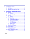
Chapter 1, Introduction, provides an overview of the tasks that may be accomplished using Local
Management (LM), and an introduction to LM screen navigation, in-band and out-of-band
network management, screen elements, and LM keyboard conventions.
Chapter 2, Local Management Requirements, provides the setup requirements for accessing
Local Management, the instructions to configure and connect a management terminal to the
SmartSwitch device, and the instructions for connecting the SmartSwitch device to an
Uninterruptible Power Supply (UPS) for monitoring the UPS power status.
Chapter 3, Accessing Local Management, describes how to access the Main Menu screen and
navigate the Local Management screens. This chapter also describes the security screens.
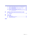
Chapter 4, Device Configuration Menu Screens, describes the Device Configuration Menu
screen and the screens that can be selected from it. These screens are used to control access to the
SmartSwitch device by assigning community names, configure the SmartSwitch device to send
SNMP trap messages to multiple network management stations, limit access according to an
Access Control List (ACL) for additional security, access system resource information, download a
new firmware image to the switch module, provide access to menu screens to configure ports, and
configure the switch module for 802.1, 802.1Q VLAN, and layer 3 operations.
Chapter 5, Port Configuration Menu Screens, describes how to use the screens to configure the
ports for various operations, such as for Ethernet Interface, HSIM/VHSIM, port and VLAN
redirect, SmartTrunk, and broadcast suppressor configuration.
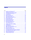
Chapter 6, 802.1 Configuration Menu Screens, describes how to access the Spanning Tree
Configuration Menu, 802.1Q VLAN Configuration Menu, and 802.1p Configuration Menu,
screens. This chapter also introduces and describes how to use the Spanning Tree screens to create
a separate Spanning Tree topology for each VLAN configured in the SmartSwitch device.
Chapter 7, 802.1Q VLAN Configuration Menu Screens, describes how to use the screens to
create static VLANs, select the mode of operation for each port, filter frames according to VLAN,
establish VLAN forwarding (Egress) lists, route frames according to VLAN ID, display the current
ports and port types associated with a VLAN and protocol, and configure ports on the switch as
GVRP-aware ports. VLAN classification and classification rules are also discussed.


