


Telnet Connections
2-4 Local Management Requirements
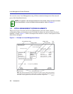
2.2 TELNET CONNECTIONS
Once the SmartSwitch device has a valid IP address, the user can establish a Telnet session from
any TCP/IP based node on the network. Telnet connections to the SmartSwitch device require the
community name passwords assigned in the SNMP Community Names Configuration screen.
For information about setting the IP address, refer to Section 4.2.
For information about assigning community names, refer to Section 4.4.
Refer to the instructions included with the Telnet application for information about establishing a
Telnet session.
If the SmartSwitch device is operating in the 802.1Q mode with configured VLANs, the
management station must be connected to a physical port on the device that is on the same VLAN
as the virtual Host Data Port. For more information about the virtual Host Data Port and the setup
information for remote management in a device that is to be configured with VLANs, refer to
Section 12.8.
2.3 MONITORING AN UNINTERRUPTIBLE POWER SUPPLY
If the SmartSwitch device is connected to an American Power Conversion (APC) Uninterruptible
Power Supply (UPS) device for protection against the loss of power, a connection from the
SmartSwitch device COM port to the UPS can be made to monitor the UPS power status. To use
the COM port for this purpose, it must be reconfigured to support the UPS connection using the
procedure described in Section 4.2.10. Refer to the UPS documentation for details on how to
access the status information.
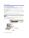
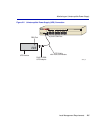
The Console Cable Kit provided with the SmartSwitch device is used to connect the UPS to the
SmartSwitch device COM port as shown in Figure 2-2. To connect the UPS device to the COM
port, proceed as follows:
1. Connect the RJ45 connector at one end of the cable to the COM port on the SmartSwitch device.
2. Plug the RJ45 connector at the other end of the cable into the RJ45-to-DB9 male (UPS) adapter
(Enterasys Networks part number, 9372066).
3. Connect the RJ45-to-DB9 male (UPS) adapter to the female DB9 port on the rear of the UPS
device (refer to the particular UPS device’s user instructions for more specific information about
the monitoring connection).