


Installing Module into Matrix E7 or Matrix N7 Chassis
Matrix DFE-Platinum Series Module Installation Guide 3-7
Installation
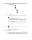
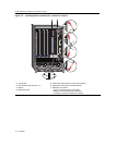
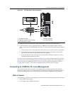
Toinstallthemodule,refertoFigure 3‐2andproceedasfollows:
1. Locatethechassiscardguidesthatlineupwiththeslotnumberinwhichthemodulewillbe
installed.Makesurethemodulelockingleversareintheopenposition(topandbottom).
2. Slidethemoduleintothechassis
cardguides,takingcarethatthemoduleslidesinstraight.
SeeCautionbelow.
3. Slidethemoduleintotheslotuntilyoucanengagethetopandbottomlockingleverswiththe
chassisasshowninFigure 3‐2.
4. RefertotheCautionnoteabove,thenrotatethetwoleversintotheclosed
position.
5. Ifthechassisinwhichthemoduleisinstalledwaspowereddownfortheinstallation,turnthe
powersupplieson.ChecktoseethatthemoduleCPULEDsettlesatsolidgreenafterafew
minutes.IftheLEDdoesnotturnsolidgreen,refertoChapter 4fortroubleshootingdetails.
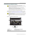
Caution: To prevent damaging the backplane connectors in the following step, take care that the
module slides in straight and properly engages the backplane connectors.
Ensure that the top lever lines up with the desired slot number located on the front panel of the
chassis. Refer to Figure 3-2.
Precaución: Para evitar que se dañen los conectores del panel posterior en el siguiente paso,
intente deslizar el módulo en forma recta y verifique que se enganche correctamente en los
conectores de panel posterior.
Asegúrese de que la palanca superior esté alineada con respecto al número de ranura
correspondiente ubicado en el panel frontal del chasis. Consulte en Figure 3-2.
Caution: Due to the amount of force needed to properly seat the module connectors into the
backplane connectors, it is best to apply force to the end of the levers to insert (or eject) the module.
Otherwise, damage could result to the module and chassis.
Precaución: Para colocar los conectores del módulo en los conectores del panel posterior
correctamente es necesario hacer bastante fuerza, por ello, para insertar o quitar el módulo, se
recomienda concentrar la fuerza en el extremo de las palancas. Si no lo hace, podría dañar el
módulo y el chasis.
Caution: In step 4, do not force the locking levers to the point that they touch the face of the front
panel. Forcing the locking levers to this point could damage the module and chassis.
Precaución: En el paso 4, tenga cuidado de no llevar las palancas de cierre a un punto en donde
estén en contacto con el panel frontal. Si lo hace, podría dañar el módulo o el chasis.