


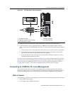
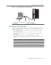


Connecting to COM Port for Local Management
Matrix DFE-Platinum Series Module Installation Guide 3-15
Adapter Wiring and Signal Assignments
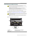
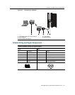
Figure 3-7 Connecting to a Modem
1 UTP straight-cable with RJ45 connectors 4 Local modem
2 RJ45 COM port 5 Remote modem
3 RJ45-to-DB25 male adapter
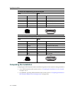
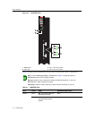
COM Port Adapter Wiring and Signal Diagram
RJ45 DB9
Pin Conductor Pin Signal
1 Blue 2 Receive (RX)
4 Red 3 Transmit (TX)
5 Green 5 Ground (GRD)
2 Orange 7 Request to Send (RTS)
6 Yellow 8 Clear to Send (CTS)
RJ45 Connector (Female)
Pins
81
69
DB9 Connector (Female)
15
Pins