


Connecting to COM Port for Local Management
Matrix DFE-Platinum Series Module Installation Guide 3-11
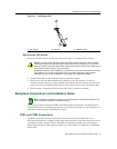
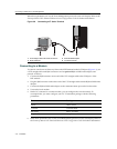
3. Attheotherendofthefiber‐opticcable,attachtheSCconnectortotheotherdevice.
4. VerifythatalinkexistsbycheckingthattheportRXLEDison(flashingamber,blinking
green,orsolidgreen).IftheRXLEDisoff,thereisnolink.Performthefollowing
stepsuntilit
ison:
a. Checkthatthedeviceattheotherendofthelinkhaspowerturnedonandiscompatible.
b. Verifypropercrossoveroffiberstrandsbetweentheportonthemoduleandthefiber‐
opticdeviceattheotherendofthefiber‐opticlinksegment.
c. Verifythat
thefiber‐opticcablemeetsthespecificationsoutlinedinAppendix Aforthe
installedEthernetexpansionmodule.
ToremovetheSCcableconnectorfromtheinterfaceport,carefullypulltheconnectoroutofthe
port.Itmayneedtobeloosenedbygentlymovingfromsidetosidetoreleasethelatching
keys.
Ifalinkhasnotbeenestablished,refertoChapter 4forLEDtroubleshootingdetails.Referto
“GettingHelp”onpagexivfordetailsoncontactingEnterasys Networksforsupport.
Connecting to COM Port for Local Management
ThissectiondescribeshowtoinstallaUTPstraight‐cablewithRJ45connectorsandoptional
adapterstoconnectaPC,aVTseriesterminal,oramodemtoanEnterasys Networksmoduleto
accessLocalManagement.Thissectionalsoprovidesthepinoutassignmentsoftheadapters.
What Is Needed
Thefollowingisalistoftheuser‐suppliedpartsthatmaybeneededdependingontheconnection:
•RJ45‐to‐DB9femaleadapter
•UTPstraight‐cablewithRJ45connectors
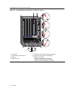
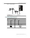
Figure 3-4 SC Fiber-Optic Cable Connection
1 SC cable connector 4 Receive LED (RX)
2 Latch keys (bottom of SC connector) 5 Transmit LED (TX)
3 SC port interface connector