


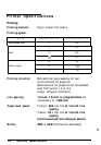
Interface Specifications
Your printer is equipped with a parallel interface
Specifications and pin assignments
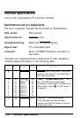
The built-in parallel interface has the following characteristics:
Data format:
B-bit parallel
Synchronization:
STROBE pulse
Handshake timing:
BUSY and ACKNLG signals
Signal level:
TTL compatible level
Connector:
36-pin 57-30360 Amphenol connector or
equivalent
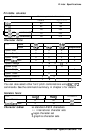
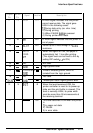
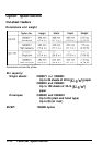
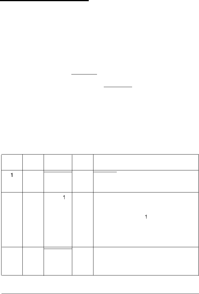
Connector pin assignments and a description of their respective
interface signals are shown in the following table.
Signal Return
Pin
Pin
Signal
Direction
Description
1
19
STROBE
in
STROBE pulse to read data. Pulse width
must be more than 0.5 microseconds at
the receiving terminal.
2
20
DATA
1
IN
These signals information of
represent
3
21
DATA 2 IN the 1st to 8th bits of parallel data,
4
22
DATA 3 IN respectively. Each signal is at HIGH level
5
23
DATA 4
IN
when data is logical
1
and LOW when
it
6
24
DATA 5
IN
is logical 0.
7
25
DATA 6
IN
8
26
DATA 7
IN
9
27
DATA 8
IN
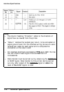
10
28
ACKNLG
OUT
About an 1 l-microsecond pulse.
LOW indicates that data has been
received and that the printer is ready to
accept more data.
7-10
Technical Specifications