


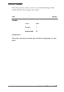
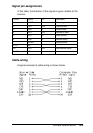
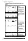
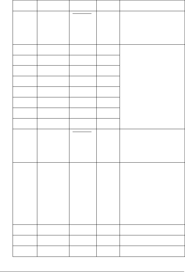
Signal pin assignments
In this table, the direction of the signals is given relative to the
scanner.
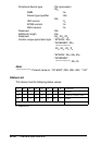
Pin No. Return pin Signal I/O Comment
1 19 STROBE IN STROBE pulse to read in
or send out data. Pulse
width must be more than
0.5 microseconds at the
receiving terminal.
2 20 DATA0 IN/OUT These signals represent
information of bits 1 to 8,
respectively. Each signal is
at a High level when data is
logical 1 and Low when it is
logical 0.
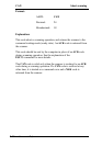
3 21 DATA1 IN/OUT
4 22 DATA2 IN/OUT
5 23 DATA3 IN/OUT
6 24 DATA4 IN/OUT
7 25 DATA5 IN/OUT
8 26 DATA6 IN/OUT
9 27 DATA7 IN/OUT
10 28 ACKNLG OUT About a 12-microsecond
pulse. Low indicates that
data has been received and
that the scanner is ready to
accept more data.
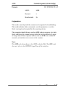
11 29 BUSY OUT When this signal is High,
the scanner cannot receive
data. The signal becomes
High:
1) during data entry,
2) during scanning,
3) when the scanner is not
ready,
4) when a scanner error
occurs.
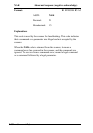
12−15 - NC - Not used
16 - GND - Logical ground level
17 - C-GND - Scanner chassis ground
Interface Specifications A-5