


Extender Series • Installation
PRELIMINARY
2-3
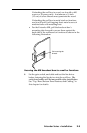
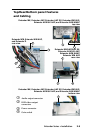
• The Extender AAP EX can also be installed into an
HSA 400 Series or HSA 800 Series surface access enclosure.
• The Extender WM can be installed in a standard or compact
one-gang electrical wall box. This is also true for the
Extender D, though it requires a standard Decora
©
-style wall
plate (not included).
• The Extender WM AUS can be installed in a standard or
compact Australian one-gang electrical wall box.
• The Extender WM AAP can be installed in a three-gang wall
box, and its faceplate accepts up to four single height Extron
Architectural Adapter Plates (AAPs).
• The Extender MK can be mounted into a standard, shallow
knockout switch box (also known as a KO box or MK
box) that is used in Singapore, the United Kingdom, and
Australia.
The installation must conform to national and local electrical
codes and to the Extender’s size requirements. Dimensional
drawings and templates are provided in appendix B of this
manual.
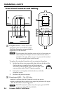
1. Refer to the template that corresponds to the Extender
model and wall box being used.
N
The templates are not shown at full size. Pay attention to
the measurements shown on the templates.
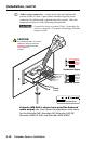
2. Mark the guidelines for the opening on the wall or
furniture.
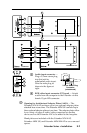
• If the Extender will be installed in a wall box, place the
box against the installation surface and draw a line on
it around the outside of the box.
• If the Extender will be installed without a wall box
(using mud rings or fastening it directly to the wall or
furniture), measure and mark the surface for the cutout
area indicated in the template.
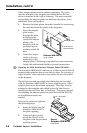
3. Cut out the material from the marked area.
4. Check the opening size by inserting the wall box (if used)
or the Extender (if no box is used) into the opening. The
box and line driver should t easily into the opening.
Enlarge or smooth the edges of the opening if needed.
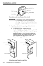
5. Feed cables through the wall box punch-out holes, and
secure them with cable clamps to provide strain relief.
6. Exposed cable shields (braids or foil) are potential sources
of short circuits. Trim back and/or insulate shields with
heat shrink.