


Extender Series • Installation
2-11
PRELIMINARY
Sleeve (s)
Left Tip
Right Tip
Left Ring
Right Ring
9-18 VDC
Power
Audio
Unbalanced Output
Left Tip
NO Ground Here
Sleeve(s)
Right Tip
NO Ground Here
Balanced Output
Sleeve(s)
Left Tip
Right Tip
Left Ring
Right Ring
L
Audio
R
L
Audio
R
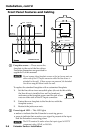
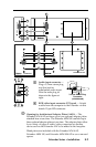
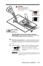
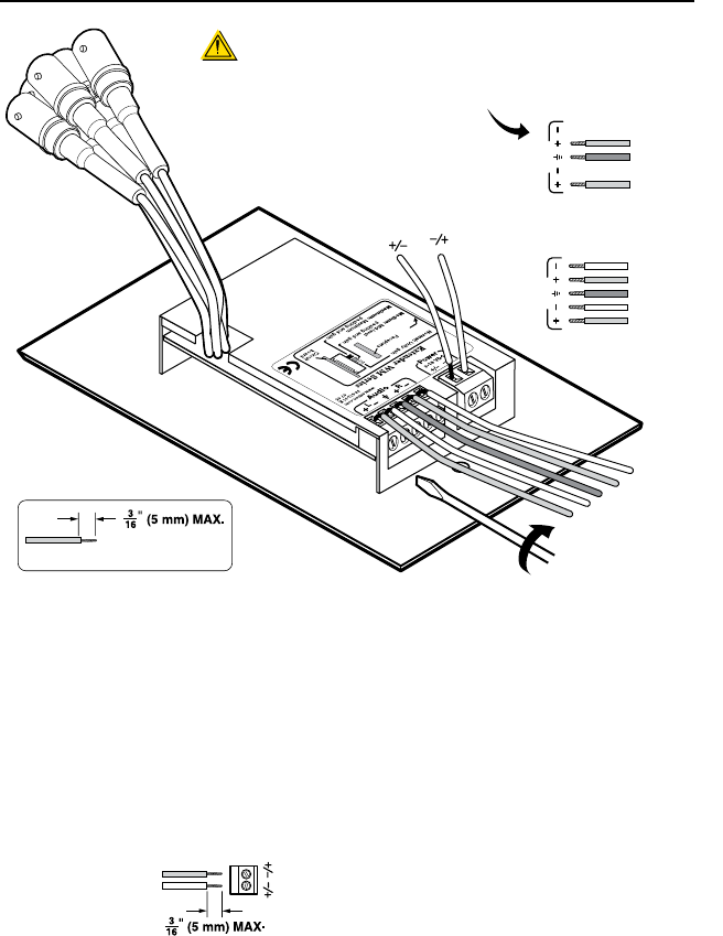
Do not tin the wires!
CAUTION
For unbalanced audio, connect the
sleeve(s) to the ground contact.
DO NOT connect the sleeve(s) to the
negative (-) contacts.
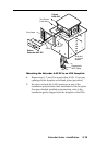
Extender WM is shown here wired for balanced
audio output; the circuit board configuration is the same
for the Extender WM AAP and the Extender D
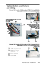
b
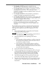
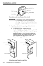
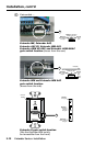
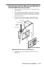
RGB video output connectors — Attach coaxial cables from the
Extender to the display device via these female BNC connectors.
These BNCs are on pigtail wires secured to the Extender by tie
wrap.
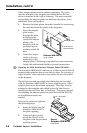
c
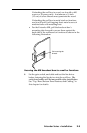
Power connector — Connect a 9 VDC to 18 VDC power supply
to this 3.5 mm, 2-pole direct insertion
captive screw connector. Wire the
connector as shown here. Polarity is not
important.
C
For best results and to reduce the risk of short circuits,
trim just
3
/
16
” (5 mm) of the jacket from the wires. Do
not tin the wires.
+ or –
– or +
9-18 VDC
Power
Do not tin the wires!