


Extender Series • Installation
Installation, cont’d
2-6
PRELIMINARY
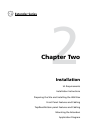
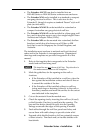
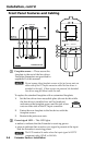
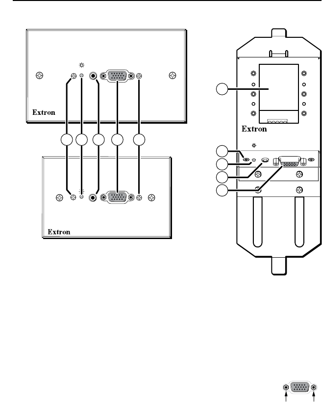
Front Panel Features and Cabling
a
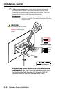
Faceplate screws — These secure the
faceplate to the rest of the line driver.
Faceplate dimensions are provided in
appendix B of this manual.
N
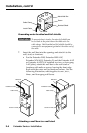
Do not remove these faceplate screws or the jack screw nuts on
either side of the PC Input connector while the line driver is
attached to the wall. If these screws are removed, the detached
line driver may fall down inside the wall.
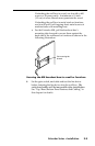
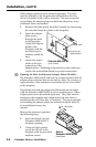
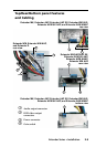
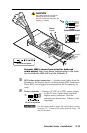
To replace the standard faceplate with a customized faceplate:
1. Set the line driver in an accessible place (do not do this while
the line driver is installed in a wall or furniture),
and remove the faceplate screws and the jack screw
nuts on either side of the PC Input connector.
2. Fasten the new faceplate to the line driver with the
faceplate screws.
3. Reattach the jack screw nuts.
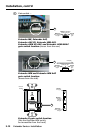
b
Power/signal LED — This LED lights
• amber to indicate that the Extender is receiving power
• green to indicate that an active sync signal is present at the input
and the Extender is receiving power
N
The LED remains lit amber when the input signal is HDTV
component video, RGsB, or RsGsBs.
EXTENDER AKM MAAP
AUDIO IN COMPUTER IN
EXTENDER MK
COMPUTER IN
AUDIO IN
EXTENDER WM AUS
COMPUTER IN
AUDIO IN
1
2
3
1
4
2 3 1 4
6
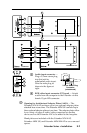
Jack Screw Nuts